Reception of the conference for publication in the EBS of the St. Petersburg State University "Leti". Reception of radio broadcasts for publication in the EBS of St. Petersburg State University "LETI" Types of slot antennas
- Translation
The article for translation was proposed by alessandro893. The material is taken from an extensive reference site, describing, in particular, the principles of operation and design of radars.
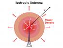
An antenna is an electrical device that converts electricity into radio waves and vice versa. The antenna is used not only in radars, but also in jammers, radiation warning systems and communications systems. During transmission, the antenna concentrates the energy of the radar transmitter and forms a beam directed in the desired direction. When receiving, the antenna collects the returning radar energy contained in the reflected signals and transmits them to the receiver. Antennas often vary in beam shape and efficiency.

Left – isotropic antenna, right – directional
Dipole antenna


A dipole antenna, or dipole, is the simplest and most popular class of antennas. Consists of two identical conductors, wires or rods, usually with bilateral symmetry. For transmitting devices, current is supplied to it, and for receiving devices, a signal is received between the two halves of the antenna. Both sides of the feeder at the transmitter or receiver are connected to one of the conductors. Dipoles are resonating antennas, that is, their elements serve as resonators in which standing waves pass from one end to the other. So the length of the dipole elements is determined by the length of the radio wave.
Directional pattern
Dipoles are omnidirectional antennas. For this reason, they are often used in communication systems.
Antenna in the form of an asymmetric vibrator (monopole)


An asymmetrical antenna is half of a dipole antenna, and is mounted perpendicular to the conducting surface, a horizontal reflecting element. The directivity of a monopole antenna is twice that of a double-length dipole antenna because there is no radiation underneath the horizontal reflective element. In this regard, the efficiency of such an antenna is twice as high, and it is capable of transmitting waves further using the same transmission power.
Directional pattern


Wave channel antenna, Yagi-Uda antenna, Yagi antenna


Directional pattern


Corner antenna

A type of antenna often used on VHF and UHF transmitters. It consists of an irradiator (this can be a dipole or a Yagi array) mounted in front of two flat rectangular reflective screens connected at an angle, usually 90°. A sheet of metal or a grating (for low-frequency radars) can act as a reflector, reducing weight and reducing wind resistance. Corner antennas have a wide range, and the gain is about 10-15 dB.
Directional pattern

Vibrator log-periodic (logarithmic periodic) antenna, or log-periodic array of symmetrical vibrators

A log-periodic antenna (LPA) consists of several half-wave dipole emitters of gradually increasing length. Each consists of a pair of metal rods. The dipoles are mounted closely, one behind the other, and connected to the feeder in parallel, with opposite phases. This antenna is similar in appearance to a Yagi antenna, but it works differently. Adding elements to a Yagi antenna increases its directivity (gain), and adding elements to an LPA increases its bandwidth. Its main advantage over other antennas is its extremely wide range of operating frequencies. The lengths of the antenna elements relate to each other according to a logarithmic law. The length of the longest element is 1/2 the wavelength of the lowest frequency, and the shortest is 1/2 the wavelength of the highest frequency.
Directional pattern

Helix antenna

A helical antenna consists of a conductor twisted into a spiral. They are usually mounted above a horizontal reflective element. The feeder is connected to the bottom of the spiral and the horizontal plane. They can operate in two modes - normal and axial.
Normal (transverse) mode: The helix dimensions (diameter and inclination) are small compared to the wavelength of the transmitted frequency. The antenna operates in the same way as a shorted dipole or monopole, with the same radiation pattern. The radiation is linearly polarized parallel to the axis of the spiral. This mode is used in compact antennas for portable and mobile radios.
Axial mode: the dimensions of the spiral are comparable to the wavelength. The antenna works as a directional one, transmitting the beam from the end of the spiral along its axis. Emits radio waves of circular polarization. Often used for satellite communications.
Directional pattern

Rhombic antenna

A diamond antenna is a broadband directional antenna consisting of one to three parallel wires fixed above the ground in the shape of a diamond, supported at each vertex by towers or poles to which the wires are attached using insulators. All four sides of the antenna are the same length, usually at least the same wavelength, or longer. Often used for communication and operation in the decameter wave range.
Directional pattern

Two-dimensional antenna array

Multi-element array of dipoles used in the HF bands (1.6 - 30 MHz), consisting of rows and columns of dipoles. The number of rows can be 1, 2, 3, 4 or 6. The number of columns can be 2 or 4. The dipoles are horizontally polarized and a reflective screen is placed behind the dipole array to provide an amplified beam. The number of dipole columns determines the width of the azimuthal beam. For 2 columns the beam width is about 50°, for 4 columns it is 30°. The main beam can be tilted 15° or 30° for maximum coverage of 90°.

The number of rows and the height of the lowest element above the ground determines the elevation angle and the size of the serviced area. An array of two rows has an angle of 20°, and an array of four has an angle of 10°. The radiation from a two-dimensional array usually approaches the ionosphere at a slight angle, and due to its low frequency, is often reflected back to the earth's surface. Since radiation can be reflected many times between the ionosphere and the ground, the antenna's action is not limited to the horizon. As a result, such an antenna is often used for long-distance communications.
Directional pattern

Horn antenna


A horn antenna consists of an expanding horn-shaped metal waveguide that collects radio waves into a beam. Horn antennas have a very wide range of operating frequencies; they can operate with a 20-fold gap in its boundaries - for example, from 1 to 20 GHz. The gain varies from 10 to 25 dB, and they are often used as feeds for larger antennas.
Directional pattern


Parabolic antenna

One of the most popular radar antennas is the parabolic reflector. The feed is located at the focus of the parabola, and the radar energy is directed to the surface of the reflector. Most often, a horn antenna is used as a feed, but both a dipole and a helical antenna can be used.

Since the point source of energy is at the focus, it is converted into a wavefront of constant phase, making the parabola well suited for use in radar. By changing the size and shape of the reflective surface, beams and radiation patterns of various shapes can be created. The directivity of parabolic antennas is much better than that of a Yagi or dipole; the gain can reach 30-35 dB. Their main drawback is their inability to handle low frequencies due to their size. Another thing is that the irradiator can block part of the signal.
Directional pattern


Cassegrain antenna


A Cassegrain antenna is very similar to a conventional parabolic antenna, but uses a system of two reflectors to create and focus the radar beam. The main reflector is parabolic, and the auxiliary reflector is hyperbolic. The irradiator is located at one of the two foci of the hyperbola. The radar energy from the transmitter is reflected from the auxiliary reflector onto the main one and focused. The energy returning from the target is collected by the main reflector and reflected in the form of a beam converging at one point onto the auxiliary one. It is then reflected by an auxiliary reflector and collected at the point where the irradiator is located. The larger the auxiliary reflector, the closer it can be to the main one. This design reduces the axial dimensions of the radar, but increases the shading of the aperture. A small auxiliary reflector, on the contrary, reduces shading of the opening, but it must be located away from the main one. Advantages compared to a parabolic antenna: compactness (despite the presence of a second reflector, the total distance between the two reflectors is less than the distance from the feed to the reflector of a parabolic antenna), reduced losses (the receiver can be placed close to the horn emitter), reduced side lobe interference for ground radars. Main disadvantages: the beam is blocked more strongly (the size of the auxiliary reflector and feed is larger than the size of the feed of a conventional parabolic antenna), does not work well with a wide range of waves.

Directional pattern

Antenna Gregory


On the left is the Gregory antenna, on the right is the Cassegrain antenna
The Gregory parabolic antenna is very similar in structure to the Cassegrain antenna. The difference is that the auxiliary reflector is curved in the opposite direction. Gregory's design can use a smaller secondary reflector compared to a Cassegrain antenna, resulting in less of the beam being blocked.
Offset (asymmetric) antenna


As the name suggests, the emitter and auxiliary reflector (if it is a Gregory antenna) of an offset antenna are offset from the center of the main reflector so as not to block the beam. This design is often used on parabolic and Gregory antennas to increase efficiency.
Cassegrain antenna with flat phase plate


Another design designed to combat beam blocking by an auxiliary reflector is the flat plate Cassegrain antenna. It works taking into account the polarization of waves. An electromagnetic wave has 2 components, magnetic and electric, which are always perpendicular to each other and the direction of movement. The polarization of the wave is determined by the orientation of the electric field, it can be linear (vertical/horizontal) or circular (circular or elliptical, twisted clockwise or counterclockwise). The interesting thing about polarization is the polarizer, or the process of filtering the waves, leaving only waves polarized in one direction or plane. Typically, the polarizer is made of a material with a parallel arrangement of atoms, or it can be a lattice of parallel wires, the distance between which is less than the wavelength. It is often assumed that the distance should be approximately half the wavelength.
A common misconception is that the electromagnetic wave and polarizer work in a similar way to an oscillating cable and a plank fence - that is, for example, a horizontally polarized wave must be blocked by a screen with vertical slits.

In fact, electromagnetic waves behave differently than mechanical waves. A lattice of parallel horizontal wires completely blocks and reflects a horizontally polarized radio wave and transmits a vertically polarized one - and vice versa. The reason is this: when an electric field, or wave, is parallel to a wire, it excites electrons along the length of the wire, and since the length of the wire is many times greater than its thickness, the electrons can easily move and absorb most of the energy of the wave. The movement of electrons will lead to the appearance of a current, and the current will create its own waves. These waves will cancel out the transmission waves and behave like reflected waves. On the other hand, when the electric field of the wave is perpendicular to the wires, it will excite electrons across the width of the wire. Since the electrons will not be able to actively move in this way, very little energy will be reflected.

It is important to note that although in most illustrations radio waves have only 1 magnetic field and 1 electric field, this does not mean that they oscillate strictly in the same plane. In fact, one can imagine that electric and magnetic fields consist of several subfields that add up vectorially. For example, for a vertically polarized wave from two subfields, the result of adding their vectors is vertical. When two subfields are in phase, the resulting electric field will always be stationary in the same plane. But if one of the subfields is slower than the other, then the resulting field will begin to rotate around the direction the wave is moving (this is often called elliptical polarization). If one subfield is slower than the others by exactly a quarter of a wavelength (the phase differs by 90 degrees), then we get circular polarization:

To convert linear polarization of a wave into circular polarization and back, it is necessary to slow down one of the subfields relative to the others by exactly a quarter of the wavelength. For this, a grating (quarter-wave phase plate) of parallel wires with a distance between them of 1/4 wavelength, located at an angle of 45 degrees to the horizontal, is most often used.
For a wave passing through the device, linear polarization turns into circular, and circular into linear.

A Cassegrain antenna with a flat phase plate operating on this principle consists of two reflectors of equal size. The auxiliary reflects only horizontally polarized waves and transmits vertically polarized waves. The main one reflects all waves. The auxiliary reflector plate is located in front of the main one. It consists of two parts - a plate with slits running at an angle of 45°, and a plate with horizontal slits less than 1/4 wavelength wide.

Let's say the feed transmits a wave with circular polarization counterclockwise. The wave passes through the quarter-wave plate and becomes a horizontally polarized wave. It is reflected from horizontal wires. It passes through the quarter-wave plate again, on the other side, and for it the plate wires are already oriented mirror-image, that is, as if rotated by 90°. The previous change in polarization is reversed, so that the wave again becomes circularly polarized counterclockwise and travels back to the main reflector. The reflector changes polarization from counterclockwise to clockwise. It passes through the horizontal slits of the auxiliary reflector without resistance and leaves in the direction of the targets, vertically polarized. In receive mode, the opposite happens.
Slot antenna


Although the described antennas have fairly high gain relative to the aperture size, they all have common disadvantages: high side-lobe susceptibility (susceptibility to nuisance reflections from the earth's surface and sensitivity to targets with a low effective scattering area), reduced efficiency due to beam blocking (small radars, which can be used on aircraft, have a problem with blocking; large radars, where the problem with blocking is less, cannot be used in the air). As a result, a new antenna design was invented - a slot antenna. It is made in the form of a metal surface, usually flat, in which holes or slots are cut. When it is irradiated at the desired frequency, electromagnetic waves are emitted from each slot - that is, the slots act as individual antennas and form an array. Since the beam coming from each slot is weak, their side lobes are also very small. Slot antennas are characterized by high gain, small side lobes and low weight. They may have no protruding parts, which in some cases is their important advantage (for example, when installed on aircraft).
Directional pattern


Passive phased array antenna (PFAR)


Radar with MIG-31
Since the early days of radar development, developers have been plagued by one problem: the balance between accuracy, range and scan time of the radar. It arises because radars with a narrower beam width increase accuracy (increased resolution) and range at the same power (power concentration). But the smaller the beam width, the longer the radar scans the entire field of view. Moreover, a high-gain radar will require larger antennas, which is inconvenient for fast scanning. To achieve practical accuracy at low frequencies, the radar would require antennas so huge that they would be mechanically difficult to rotate. To solve this problem, a passive phased array antenna was created. It relies not on mechanics, but on the interference of waves to control the beam. If two or more waves of the same type oscillate and meet at one point in space, the total amplitude of the waves adds up in much the same way as waves on water add up. Depending on the phases of these waves, interference can strengthen or weaken them.

The beam can be shaped and controlled electronically by controlling the phase difference of a group of transmitting elements - thus controlling where amplification or attenuation interference occurs. It follows from this that the aircraft radar must have at least two transmitting elements to control the beam from side to side.


Typically, a PFAR radar consists of 1 feed, one LNA (low noise amplifier), one power distributor, 1000-2000 transmitting elements and an equal number of phase shifters.

Transmitting elements can be isotropic or directional antennas. Some typical types of transmission elements:

On the first generations of fighter aircraft, patch antennas (strip antennas) were most often used because they were the easiest to develop.

Modern active phase arrays use groove emitters due to their wideband capabilities and improved gain:


Regardless of the type of antenna used, increasing the number of radiating elements improves the radar's directivity characteristics.


As we know, for the same radar frequency, increasing the aperture leads to a decrease in beam width, which increases range and accuracy. But for phased arrays, it is not worth increasing the distance between the emitting elements in an attempt to increase the aperture and reduce the cost of the radar. Because if the distance between the elements is greater than the operating frequency, side lobes may appear, significantly degrading the radar's performance.


The most important and expensive part of the PFAR is the phase shifters. Without them, it is impossible to control the signal phase and beam direction.


They come in different types, but generally they can be divided into four types.
Phase shifters with time delay


The simplest type of phase shifters. It takes time for a signal to travel through a transmission line. This delay, equal to the phase shift of the signal, depends on the length of the transmission line, the frequency of the signal, and the phase velocity of the signal in the transmitting material. By switching a signal between two or more transmission lines of a given length, the phase shift can be controlled. Switching elements are mechanical relays, pin diodes, field-effect transistors or microelectromechanical systems. Pin diodes are often used because of their high speed, low loss, and simple bias circuits that provide resistance changes from 10 kΩ to 1 Ω.
Delay, sec = phase shift ° / (360 * frequency, Hz)
Their disadvantage is that the phase error increases with increasing frequency and increases in size with decreasing frequency. Also, the phase change varies with frequency, so they are not applicable for very low and high frequencies.
Reflective/quadrature phase shifter


Typically this is a quadrature coupling device that splits the input signal into two signals 90° out of phase, which are then reflected. They are then combined in phase at the output. This circuit works because signal reflections from conductive lines can be out of phase with respect to the incident signal. The phase shift varies from 0° (open circuit, zero varactor capacitance) to -180° (shorted circuit, infinite varactor capacitance). Such phase shifters have a wide range of operation. However, the physical limitations of varactors mean that in practice the phase shift can only reach 160°. But for a larger shift it is possible to combine several such chains.
Vector IQ modulator


Just like a reflective phase shifter, here the signal is split into two outputs with a 90-degree phase shift. The unbiased input phase is called the I-channel, and the quadrature with a 90-degree offset is called the Q-channel. Each signal is then passed through a biphasic modulator capable of shifting the phase of the signal. Each signal is phase shifted by 0° or 180°, allowing any pair of quadrature vectors to be selected. The two signals are then recombined. Since the attenuation of both signals can be controlled, not only the phase but also the amplitude of the output signal is controlled.
Phase shifter on high/low pass filters

It was manufactured to solve the problem of time delay phase shifters not being able to operate over a large frequency range. It works by switching the signal path between high-pass and low-pass filters. Similar to a time delay phase shifter, but uses filters instead of transmission lines. The high-pass filter consists of a series of inductors and capacitors that provide phase advance. Such a phase shifter provides a constant phase shift in the operating frequency range. It is also much smaller in size than the previous phase shifters listed, which is why it is most often used in radar applications.
To summarize, compared to a conventional reflective antenna, the main advantages of PFAR will be: high scanning speed (increasing the number of tracked targets, reducing the likelihood of the station detecting an radiation warning), optimization of the time spent on the target, high gain and small side lobes (difficult to jam and detect), random scan sequence (harder to jam), ability to use special modulation and detection techniques to extract signal from noise. The main disadvantages are high cost, the inability to scan wider than 60 degrees in width (the field of view of a stationary phase array is 120 degrees, a mechanical radar can expand it to 360).
Active phased array antenna


Outside, AFAR (AESA) and PFAR (PESA) are difficult to distinguish, but inside they are radically different. PFAR uses one or two high-power amplifiers to transmit a single signal, which is then divided into thousands of paths for thousands of phase shifters and elements. An AFAR radar consists of thousands of reception/transmission modules. Since the transmitters are located directly in the elements themselves, it does not have a separate receiver and transmitter. The differences in architecture are shown in the picture.

In AFAR, most of the components, such as a weak signal amplifier, a high-power amplifier, a duplexer, and a phase shifter, are reduced in size and assembled in one housing called a transmit/receive module. Each of the modules is a small radar. Their architecture is as follows:


Although AESA and PESA use wave interference to shape and deflect the beam, the unique design of AESA provides many advantages over PFAR. For example, a small signal amplifier is located close to the receiver, before the components where part of the signal is lost, so it has a better signal-to-noise ratio than a PFAR.


Moreover, with equal detection capabilities, AFAR has a lower duty cycle and peak power. Also, since individual APAA modules do not rely on a single amplifier, they can transmit signals at different frequencies simultaneously. As a result, AFAR can create several separate beams, dividing the array into subarrays. The ability to operate on multiple frequencies brings multitasking and the ability to deploy electronic jamming systems anywhere in relation to the radar. But forming too many simultaneous beams reduces the radar's range.

The two main disadvantages of AFAR are high cost and limited field of view to 60 degrees.
Hybrid electronic-mechanical phased array antennas


The very high scanning speed of the phased array is combined with a limited field of view. To solve this problem, modern radars place phased arrays on a movable disk, which increases the field of view. Do not confuse the field of view with the width of the beam. Beam width refers to the radar beam, and field of view refers to the overall size of the space being scanned. Narrow beams are often needed to improve accuracy and range, but a narrow field of view is usually not necessary.

Tags: Add tags
Radio magazine, number 9, 1999.
Judging by foreign amateur radio literature, the skeleton-slot antenna is popular at frequencies above 20 MHz. The published article attempts to answer the question - to what extent its directional coefficient stated in the literature corresponds to reality.
In books on VHF antennas, the so-called skeleton-slot antenna has been repeatedly described, and all publications, without exception, reported on its very high parameters, large directivity coefficient (DA), wide frequency band and ease of tuning. The idea of the antenna was proposed by J. Ramsey back in 1949, its design is shown in Fig. 1,borrowed from . The active element of the antenna consists of three parallel half-wave dipoles located three levels above each other.
To reduce the size of the antenna, the ends of the upper and lower dipoles are bent at right angles towards the middle dipole and connected to it. This is what gets them excited. The middle dipole is made split and connected to a matching quarter-wave two-wire line, which also serves to mount the reflector. The reflector is designed like a wave channel in the form of a single vibrator, the electrical length of which is slightly greater than a half-wave. The dimensions of the antenna in wavelengths and the values of the shortening coefficient k, depending on the diameter of the conductors (tubes) d, are shown in Fig. 1. By moving the feed point XX along the two-wire line, you can change the input impedance of the antenna from zero (near the reflector) to approximately 400 Ohms (at point YY near the active element).
The current distribution in the active element is shown in Fig. 2. It can be seen that the antinodes (maxima) of the current are located exactly in the middle of the horizontal parts of the element, forming a three-story in-phase system. In the vertical parts of the active element, the currents are small and directed towards each other. In addition, there are four current nodes here, so there is no far-field radiation from the vertical parts. Let us recall that in the far zone the antenna radiation pattern is almost completely formed. The distance to the far zone is several wavelengths. The greater the antenna efficiency, the greater it is.

The active element of a skeleton-slot antenna can also be considered as two squares, combined with one side and feed points. However, compared to two full-size squares, the perimeter of the active element of the skeleton-slot antenna is somewhat smaller, probably due to the shortening effect of the capacitance between the vertical conductors of the element. A similar antenna was proposed by K. Kharchenko, but in it two squares are fed from the corners and combined with feed points.
A simple skeleton-slot antenna has a reflector that is not efficient enough. This drawback can be eliminated by constructing the reflector in exactly the same way as the active element (in the form of the same three-story structure of vibrators). Two-wire lines can no longer be placed between the elements, but no one bothers to draw them in the plane of each element to a point with zero potential in the middle of the lower horizontal vibrator.
What happens after this modification is shown in Fig. 3. The dimensions of the elements themselves remain the same, and the distance between the active element and the reflector is reduced to 0.18. This antenna has one more advantage. By moving short-circuiting jumpers along two-wire lines, the elements can be adjusted to the desired frequency, and by moving the reflector jumper, it is easy to adjust the antenna to the maximum efficiency or forward-backward radiation ratio.

For such a two-element antenna, described in [and], an unusually high efficiency of 14...16 dB is reported! If the second of the books mentioned was not a serious publication, then one could still give up and not take this figure seriously. But this book is overall very good and contains almost no errors. Its author, of course, could not test all the many constructions given in it. Therefore, if this is an error, then it appeared earlier, in some other publications, and it is now difficult to find the original source. It is quite clear that an in-phase system of vibrators should give greater efficiency than a single vibrator, but the question is - how much? Although on p. 100 and it is stated that the antenna “... is actually a six-element, three-story in-phase antenna,” but the vibrators are quite close to each other, and also shortened. This must inevitably reduce efficiency. Thus, there were more questions than answers. In addition, radio amateurs familiar to the author were planning to build just such an antenna for the 10-meter range and were ready to spend money on the material, which is not cheap these days!
To get a clear and precise answer to the question about the directivity factor, an experiment was conducted in the 432 MHz range. The elements were bent in accordance with Fig. 3 pieces of enameled copper wire with a diameter of 1.5 mm, the connections are soldered, and the line conductors in the places where the closing jumpers are installed and the cable is connected are stripped of insulation. The entire structure was assembled on a wooden frame made of dry thin slats. The power cable ran from the power points along the two-wire line conductor to which the braid was connected, vertically down and connected directly to the output of the standard signal generator. The field indicator was a half-wave dipole with a detector and a microammeter. It was located on a tripod at a distance of several meters from the antenna. The antenna was also mounted on a primitive rotating tripod, which made it possible to change its orientation.
The antenna was tuned quite easily and quickly, just for maximum radiation in the main direction. With the indicated dimensions at a frequency of 432 MHz, the distances of the closing jumpers from the base of the two-wire lines for the tuned antenna turned out to be as follows: for the reflector - 43 mm, for the active element - 28 mm. The distance to the connection point of the 50-ohm cable was 70 mm.
When adjusted to maximum directivity, a small back lobe is detected. By adjusting the reflector, it can be suppressed almost completely. There was no sideways, up or down radiation.
The efficiency, or more precisely, the gain of the antenna, equal to the product of the efficiency and efficiency, was determined as follows: the signal level created by the antenna in the main direction was noted on the indicator, then, instead of the antenna, a half-wave dipole located at the same point in space was connected to the power cable. The signal level from the generator increased enough to obtain the same readings on the indicator. The change in signal level measured by the generator attenuator is numerically equal to the gain of the antenna relative to the half-wave dipole. For this antenna it turned out to be 7 dBd. Compared to an isotropic (omnidirectional) emitter, it will be 2.15 dB more and will be about 9.2 dBi.
Pay attention to the letters d and i in the designation of decibels - in the literature on antennas this is how it is customary to indicate relative to which emitter the directivity is measured. The width of the radiation pattern at half power was about 60° in the horizontal plane (in azimuth), and about 90° in the vertical plane (in elevation). Having this data, the directivity can be calculated in one more way: the solid angle into which the antenna radiates is equal to the product of linear angles corresponding to the width of the diagram and expressed in radians. We get a value of about 1.5 steradians. At the same time, an isotropic antenna radiates into a solid angle of 4, or 12.6 steradians. The directivity, by definition, is the ratio of these solid angles and is 12.6/1.5 = 8.4 or 9.2 dBi.
Having obtained such a good agreement between the directivity values determined by the two methods, the author decided that there was nothing more to measure and, with slight disappointment, he was once again convinced that miracles do not happen in antenna technology. Nevertheless, the antenna works very well and, despite its small dimensions (330x120x120 mm in the 432 MHz range), provides a very decent gain.
The invention relates to antenna-feeder devices, namely to ultrashort radio wave antennas and microwave antennas for emitting horizontally polarized waves with a circular radiation pattern in the horizontal plane. The technical result achieved from the implementation of the proposed invention is the expansion of the operating frequency range of the slot cylindrical antenna, providing the antenna with devices for matching with the feeder, which are not critical to size when tuning the antenna to the operating resonant frequency. The slot cylindrical antenna contains a conducting cylindrical body with a longitudinal slot with first and second edges and a feeder, additionally containing a first conductive clamp, a second conducting clamp and a matching cable section, wherein the first clamp is located to form a galvanic contact on the first edge of the slot, the second clamp is located with by forming a galvanic contact on the second edge of the slot, the feeder on the surface of the cylinder is laid along a straight line diametrically opposite to the longitudinal axis of the slot, with a bend in the vicinity of the point of excitation of the slot, laid through the first clamp with the outer conductor of the feeder forming a galvanic contact with the first clamp, a matching section of cable is laid through the second clamp, the central conductor of the feeder is galvanically connected to the central conductor of the matching cable section. 1 salary f-ly, 6 ill.
Drawings for RF patent 2574172


Field of technology to which the invention relates
The invention relates to antenna-feeder devices, namely to ultrashort radio wave antennas and microwave antennas for emitting horizontally polarized waves with a circular radiation pattern in the horizontal plane.
State of the art
The slot antenna was first proposed in 1938 by Alan D. Blumlein for use in television broadcasting in the ultrashort wave range with horizontal polarization and a circular radiation pattern (RP) in the horizontal plane [British patent No. 515684. HF electrical conductors. Alan Blumlein, publ. 1938. US patent No. 2,238,770 High frequency electrical conductor or radiator]. The antenna is a pipe with a longitudinal slot. The simplicity of the design, the absence of a protruding part above the surface in which a slot is cut, attracted the attention of specialists designing radio systems for submarines. Slot antennas do not disrupt the aerodynamics of the objects on which they are installed, which has determined their widespread use on aircraft, missiles and other moving objects. Such antennas with slots cut into the walls of waveguides of rectangular, circular or other cross-sectional shapes are widely used as airborne and ground-based antennas for radar and radio navigation systems.
So, the first slotted cylindrical antenna A.D. is known. Blumlein for emitting horizontally polarized waves of high frequencies, containing a conducting cylinder with a longitudinal slit, devices for exciting the slit at one end of the cylinder and a short circuit at the other end of the cylinder, a device for adjusting the width of the slit. The conducting cylinder has a length equal to half the wavelength in free space.
The disadvantages of the known first slot antenna are that:
The antenna does not contain devices for tuning the antenna to the resonant frequency,
The antenna has a length equal to half the wavelength in free space, which makes it difficult to obtain acceptable antenna performance in terms of directional properties and antenna-to-feed matching.
A second cylindrical slot antenna is known for emitting horizontally polarized high-frequency waves, containing a conducting cylinder with a longitudinal slot, a feeder, a short circuit at one end of the slot and devices for exciting the antenna at the other end of the slot, said cylinder has a diameter of between 0.151 and 0.121, where 1 - wavelength in free space at the operating frequency. The said cylinder has a length close to nine-tenths of a quarter of the length of the standing wave established along the slot line on the cylinder (the wavelength in the slot line on the cylinder is several times greater than the wavelength in free space).
When the cylinder is vertically oriented, the antenna has an almost circular radiation pattern with horizontal polarization of the radiation field and has a high directivity coefficient (DA). The antenna is compact, convenient for installation on the roofs of tall buildings, its smooth surface contours prevent the accumulation of wet snow and ice formation. Due to its circular cylindrical shape, the antenna has a relatively low wind load.
The known second antenna overcomes the disadvantages of the first known antenna due to its size of half a wavelength in free space. Andrew Alford's omnidirectional slot antenna, created in 1946 and installed on the Chrysler Skyscraper in New York, was used for the first color television broadcasts.
However, the known second slot cylindrical antenna has the following disadvantages:
the antenna has a large longitudinal size in terms of wavelengths in free space, which makes it difficult to use it as a radiating element of an antenna array that forms a radiation pattern of a special type in the plane of vector H;
the antenna does not have devices for matching it with the feeder.
A third slot cylindrical antenna is known for emitting horizontally polarized waves of high frequencies, containing a conducting cylinder with a longitudinal slot, short-circuited at both ends of the cylinder, excited by a coaxial cable, the outer conductor of which is galvanically connected to the first edge of the slot, and the central conductor is galvanically connected to the second edge of the slot.
The known third slot cylindrical antenna has disadvantages:
Due to the asymmetrical excitation of the antenna, a wave is excited that propagates in the line formed by the outer conductor of the coaxial cable and the cylinder, as a result of which noticeable radiation of the cable is observed (antenna feeder effect), its characteristics significantly depend on external operational factors;
There are no devices for matching the antenna with the feeder (to tune the antenna to resonance at the operating frequency),
The known third slot cylindrical antenna has a narrow range of operating frequencies, not exceeding 1% at the SWR level in the power line.
The third known slot cylindrical antenna, fed by a coaxial cable, is, in terms of its essential features, closest to the present invention. This antenna is selected by the authors as a prototype.
Disclosure of the Invention
The technical objective of the present invention is to expand the operating frequency range of a slotted cylindrical antenna, providing the antenna with devices for matching with the feeder, which are not size-critical when tuning the antenna to the operating (resonant) frequency.
This task is achieved in that a slotted cylindrical antenna containing a conductive cylindrical body (hereinafter referred to as the body) with a longitudinal slot with first and second edges and a feeder, additionally contains a first conductive clamp, a second conductive clamp (hereinafter referred to as the first clamp, the second clamp) and a matching a piece of cable, with the first clamp located to form a galvanic contact on the first edge of the slot, the second clamp located to form a galvanic contact on the second edge of the slot, the feeder on the surface of the cylinder is laid along a straight line diametrically opposite to the longitudinal axis of the slot, with a bend in the vicinity of the excitation point slot, laid through the first clamp with the formation of galvanic contact by the outer conductor of the feeder with the first clamp, the matching cable section is laid through the second clamp, the central conductor of the feeder is galvanically connected to the central conductor of the matching cable section.
The introduction of a first conductive clamp, a second conductive clamp and a matching section of cable into the antenna, their relative position and connection in the antenna as indicated above solves the following problems:
Create an antenna that, due to a symmetrical power system, provides a symmetrical radiation pattern in the plane of vector H, without bifurcation of the diagram and without deviation of the maximum of the radiation pattern from the plane perpendicular to the cylinder axis;
Create an antenna that provides a circular radiation pattern in the vector plane due to the fact that the diameter of the cylinder is much smaller than the wavelength;
To create an antenna that provides stable radiation characteristics when using both narrow slits with low wave impedance and wide slits with high wave impedance;
Create an antenna that provides compensation for the reactive component of the antenna input impedance in a wide frequency range;
Create an antenna whose radiation resistance varies within a small range over a wide frequency range;
Create an antenna that provides low SWR in the power line by matching the input impedance of the antenna with the characteristic impedance of the feeder over a wide frequency band;
Reduce the power level returning to the transmitter when the antenna is transmitting by matching the antenna with the feeder;
Reduce the level of distortion of the spectrum of the signal transmitted (received) by the antenna due to the uniform amplitude-phase characteristic of the antenna in the frequency range;
Increase the antenna's resistance to high-frequency breakdown by reducing the field strength in the radio frequency connector due to a decrease in the SWR in the power line when the antenna is operating in transmit mode;
Provide the antenna with a matching device by changing the reactance of the matching device and thereby expand the operating frequency band of the antenna;
Provide a simple method for tuning the antenna in coordination with the feeder in the frequency range;
Ensure maximum power transfer by matching the characteristic impedance of the feeder;
Increase the potential power level in a pre-selected feeder by reducing the SWR in it;
Minimize losses in the feeder and, as a result, reduce the heating of the feeder when transmitting power through it;
Minimize the emission (reception) of electromagnetic waves by the feeder (the outer side of the outer conductor of the coaxial cable);
Create a slot antenna that could be used as an independent antenna, as well as an element of an antenna array;
Create an antenna convenient for mounting on a pipe or belt of a lattice tower.
The antenna is compact; when the cylinder is oriented vertically, it emits horizontally polarized waves. Can serve as a radiating element of an antenna array. The antenna array of slot emitters can be installed both directly on the earth's surface and on the roofs of tall buildings. The smooth contours of the antenna surface prevent the accumulation of wet snow and ice formation on it. Due to its circular cylindrical shape, the antenna has a relatively low wind load.
By including a radome in the antenna, the problem of protecting the slotted cylindrical antenna in accordance with this invention from the influence of external operational factors is solved.
The solution to the above problems indicates that a new slot cylindrical antenna has been created that provides performance characteristics in a wide frequency range.
The solution to the first of these problems was obtained as a result of the fact that the proposed slot cylindrical antenna is excited symmetrically relative to the middle of the slot.
The operating frequency range of the proposed antenna on the side of shorter waves is limited by changes in the shape of the radiation pattern (DP). Use slits of such a length that the pattern has only one maximum, oriented perpendicular to the antenna axis. A decrease in wavelength with constant slit dimensions can lead to the appearance of two maxima deviated from the antenna axis.
The increase in wavelength is limited by a decrease in the directivity coefficient (DA). It turns out to be significant if the diameter of the cylinder is less than 0.12 wavelengths in free space.
The proposed antenna can be tuned in the specified frequency range.
The solution to the problem of creating a circular radiation pattern in the vector plane is obtained due to the fact that the diameter of the cylinder is much smaller than the wavelength in free space.
The solution to the third problem, namely providing a wide range of operating frequencies with both narrow and wide slots, was obtained by compensating for the reactive component of the antenna input impedance.
The solution to the problem of providing a simple method for compensating the reactive component of the antenna input impedance in the frequency range is achieved by using two series-connected capacitors for compensation.
Solution to the problem: to minimize the emission (reception) of electromagnetic waves by the feeder - obtained by rationally placing the feeder on the surface of the cylinder, introducing the first conductive clamp into the antenna, ensuring galvanic contact of the outer conductor with the first clamp along its entire circumference at the exit from the clamp.
Brief description of drawings
In fig. 1a) shows a slotted cylindrical antenna 1 in accordance with the present invention. In fig. 1b) shows a front view of a slot cylindrical antenna, Fig. 1c) shows a top view of a slot cylindrical antenna. In fig. 1b) and fig. 1c) the following notation has been introduced:
1 - slot cylindrical antenna,
2 - cylindrical body,
4 - first edge of the slot,
5 - second edge of the slot,
7 - first clamp,
8 - second clamp,
9 - matching cylinder,
10 - matching cable section,
11 - bending of the feeder (at the turn from the vertical section to the horizontal section located in the vicinity of the slot excitation point),
A - region of excitation of the gap.
In fig. 2a) shows region A of the gap excitation. In fig. 2b) shows the connection of the outer conductor of the feeder with the first clamp and the first edge of the slot, the antenna input impedance matching device and its connection with the second edge of the slot. In fig. 2c) shows in section the connection of the outer conductor of the feeder with the second clamp and the second edge of the slot, the matching cylinder and the matching cable section. In fig. 2b) and fig. 2c) the following notations are additionally introduced:
12 - central conductor of the matching cable section,
13 - central conductor of the feeder,
14 - external conductor of the feeder.
In fig. 3 shows the equivalent circuit of the antenna; in fig. 3 new designations have been introduced:
15 - capacitance of the capacitor formed by the inner surface of the matching cylinder 9 and the outer surface of the outer conductor of the matching cable section 10,
16 - capacitance of the capacitor formed by the inner surface of the outer conductor and the central conductor of the matching section of cable 10,
17 - inductance due to the flow of currents along the inner and outer surfaces of the pipe from the first edge to the second edge of the slot (in the absence of capacitors 15 and 16),
18 - real part of the antenna input impedance (before connecting capacitors 15 and 16),
19 - conditional terminal corresponding to the point of galvanic contact of the outer conductor of the feeder through the first conductive clamp with edge 4,
20 - conditional terminal corresponding to the point at the input of the central conductor of the matching cable section,
21 - point of galvanic contact of the matching cylinder through the conductive clamp 2 with the edge 5 of the slot 3.
In fig. Figure 4 shows the experimental dependences of the real and imaginary parts of the input resistance and SWR on the frequency of the first and second samples of a slotted cylindrical antenna; in fig. 4 notation introduced:
221 - frequency dependence of the real part of the input impedance of the first sample with a matching cable section 10.5 mm long,
222 - dependence on the frequency of the imaginary part of the input resistance of the first sample with a matching cable section 10.5 mm long,
223 - frequency dependence of the SWR antenna of the first sample with a matching cable section 10.5 mm long,
231 - dependence on the frequency of the real part of the input resistance of the second sample with a matching cylinder 11.5 mm long and a matching cable section 20.5 mm long,
232 - dependence on the frequency of the imaginary part of the input resistance of the second sample with a matching cylinder 11.5 mm long and a matching cable section 20.5 mm long,
233 - frequency dependence of the SWR antenna of the second sample of the second sample with a matching cylinder 11.5 mm long and a matching cable segment 20.5 mm long,
241 - frequency dependence of the real part of the input resistance of the second sample with a matching cylinder 7 mm long and a matching cable section 24 mm long,
242 - dependence on the frequency of the imaginary part of the input resistance of the second sample with a matching cylinder 7 mm long and a matching cable section 24 mm long,
243 - frequency dependence of the SWR antenna of the second sample with a matching cylinder 7 mm long and a matching cable section 24 mm long,
251 - frequency dependence of the real part of the input resistance of the second sample with a matching cylinder 5 mm long and a matching cable section 30 mm long,
252 - dependence on the frequency of the imaginary part of the input resistance of the second sample with a matching cylinder 5 mm long and a matching cable section 30 mm long,
253 - frequency dependence of the SWR antenna of the second sample with a matching cylinder 5 mm long and a matching cable section 30 mm long,
In fig. Figure 5 shows examples of the distribution of the electric field strength along the transmission line 26, which is a longitudinal slot on the cylinder, and along the two-wire line used to excite the said transmission line: a) the frequency of the generator is less than the critical frequency of the main wave of the slot line on the circular cylinder, b) the frequency of the generator approximately equal to the critical frequency of the main wave of the slot line on a circular cylinder, c) the frequency of the generator is greater than the critical frequency of the main wave of the slot line on a circular cylinder.
In fig. 5 the following notations are introduced:
27 - concentrated voltage source,
28 - two-wire transmission line,
29 - electric field strength vectors.
In fig. Figure 6 shows the structure of the electric field at a certain moment in time in the internal and external regions of the slot cylindrical antenna in a section perpendicular to the antenna axis. In fig. 6 the following notations are introduced: 30 - electric field lines.
In fig. 7 shows an example of using a slot cylindrical antenna of the present invention as an element of an antenna array.
Carrying out the invention
Referring to FIG. 1b, which shows a slot antenna 1 in accordance with the present invention. The antenna is made in the form of a cylindrical body 2 with a slot 3 with a first edge 4 and a second edge 5, a feeder 6, a first conductive clamp 7, a second conductive clamp 8, a matching cylinder 9, a matching section of cable 10 and fasteners.
The cylindrical body 2 is made of a conductive material such as, for example, brass, aluminum alloy, steel or other metal, or a metal alloy with good conductivity. A cylindrical body with 2 in cross section has the shape of a circle. The cross-section of the body may have the form of a square, rectangle, ellipse or other curved shaped profile.
The slot 3 is made in the cylindrical body 2 to the entire depth of the body wall by milling, laser cutting or other mechanical operation to form the first edge 4 and the second edge 5, parallel to the longitudinal axis of the cylindrical body.
A serial coaxial cable can be used as feeder 6. For clarity, matching cylinder 9 is shown as a segment of a circular cylinder.
For clarity, the matching section of cable 10 is shown as a short section of coaxial line. The matching section of cable 10 is partially located inside the matching cylinder 9, and partially outside 9.
The matching cylinder 9, clamps 7 and 8 are made of highly conductive material, for example brass or aluminum alloy. To ensure soldering, they are coated, for example, with a tin-bismuth alloy.
The end of the matching cable section 10, opposite the slot, is open and not connected to anything. The central conductor 11 of the matching section of cable 10 comes out of the matching cylinder 9 and extends to the middle of the slot 3.
The above devices and parts are mutually located relative to each other and are connected to each other as follows.
The first clamp 7 is fixed to form a galvanic contact on the first edge 4 of the slot, the second clamp 8 is fixed to form a galvanic contact on the second edge 5 of the slot, the feeder 6 on the surface of the cylinder 2 is fixed along a straight line diametrically opposite to the longitudinal axis of the slot, with a bend 13 in the vicinity point of excitation of the slot, then laid through the first clamp 7 with the formation of galvanic contact by the outer conductor 14 of the feeder with the first clamp 7, the matching section of cable 10 is laid inside the matching cylinder, which is covered by the second clamp, the central conductor 12 of the feeder is galvanically connected to the central conductor 11 of the matching cable section .
The second end of feeder 6 is installed in a radio frequency connector. In this case, as a matching section of cable 10, either a section of a standard coaxial cable or a section of a special transmission line is used, consisting of an outer conductor in the form of a tube, a central conductor in the form of a rod or tube, and a hollow dielectric cylinder located between them.
To fasten the feeder 6 to the cylindrical body 2, standardized clamps, screws and nuts can be used.
Antenna operating principle
The antenna works as follows. Electromagnetic oscillations in the antenna are excited as a result of the application of a potential difference at two points 19 and 20, opposite each other on the first 4 and second 5 edges of the slot 3. To effectively excite the antenna, the diameter of the pipe 2 must be chosen such that the generator frequency is higher than the critical frequency main wave H 00 slot line on a cylindrical waveguide. To illustrate this point, three situations presented in Fig. 1 were considered (using a rigorous solution to the boundary value problem of electrodynamics) using a model problem. 5.
In fig. 5 shows a slot line on a circular waveguide, connected in series with a two-wire line, to the end of which a voltage generator is connected. In fig. Figure 5 shows examples of the distribution of electric field strength along the transmission line for the following cases: a) the generator frequency is less than the critical frequency of the main wave of the slot line on a circular cylinder, b) the generator frequency is approximately equal to the critical frequency of the main wave of the slot line on a circular cylinder, c) the generator frequency is greater critical frequency of the fundamental wave of the slot line on a circular cylinder. In fig. 5, the electric field strength is proportional to the length of the vector. As can be seen from Fig. 5, in case a) the electromagnetic wave is reflected practically from the entrance to the transmission line. The wave penetrates into the slot line to a depth that is negligibly small in the lengths of the will. In case b) an exponentially decreasing field distribution is established in the slotted cylindrical transmission line. In case c) a standing wave is established in a slotted cylindrical transmission line. In this case, the length of the standing wave in the slot transmission line is greater than the length of the standing wave in the two-wire transmission line.
It is preferable to select a pipe diameter equal to 0.14 wavelength in free space. It is advisable to choose the slit length close to half the wavelength of the main wave H 00 of the slot line on a cylindrical waveguide
The width of the slit 3 does not exceed one-thirtieth of the wavelength. Therefore, the unevenness in the distribution of current on the central conductor of the cable within the slot 3 can be practically neglected. Consequently, the unbalanced coaxial cable is introduced into the excitation region of the antenna in such a way that it does not violate either the physical or electrical symmetry of the antenna. The displacement currents arising between the outer conductor of the feeder 6 and the housing 2 in the area from the bend of the feeder to the slot are small due to the fact that the outer conductor of the feeder 6 and the housing 2 have galvanic contact with each other through the first conductive clamp 7. Galvanic contact of the outer conductor of the feeder 6 and housing 2 causes the electric field strength to be equal to zero at the point of their connection. In a section of the feeder located along a straight line diametrically opposite to the axis of the slot, displacement currents between the outer conductor of feeder 6 and housing 2 are not excited, since in this section of the path the potential is zero. Therefore, the potential radiation from the gap formed between the outer conductor of the feeder 6 and the housing 2 can be neglected. Thus, the antenna effect of the feeder and the associated unpredictable distortions of the antenna radiation pattern, changes in the antenna input impedance, and cross-polarized field radiation are eliminated. Using a rigorous solution of Maxwell's equations under given ideal boundary conditions, the electric field lines were calculated by the time method at different times during one period of generator voltage oscillations. Field lines at some point in time are shown in Fig. 6. For the convenience of designating antenna elements by numbers, the moment in time was chosen when the electric field strength in the immediate vicinity of the slot is small, therefore there are no lines of force in this vicinity in Fig. 6. Far from the slit, already formed field vortices are observed, represented by lines of force that are not supported by charges on the walls of the cylinder. In the intermediate zone, the force lines originate on the lower half of the cylinder in the presented drawing and end their path on the upper part of the cylinder. At the point opposite the center of the slit, the line of force does not take and end its path, since the potential at this point is zero. This point is the boundary point between the lower and upper halves of the cylinder. According to the above rule, the force line should begin and end its path here. However, this turns out to be impossible, because the electric field strength vectors tangent to the lower and upper parts of the field line are opposite to each other at this point and, therefore, cancel each other. For this reason, the vicinity of the line opposite the slit axis turns out to be convenient for laying a feeder along it in order to minimize the antenna effect of the feeder.
The above antenna design provides convenient adjustment of the alignment of the antenna with the feeder. Let us consider this in more detail by referring to the equivalent antenna circuit in FIG. 3. In FIG. 3, the number 15 denotes the first capacitor with capacitance C 1, formed by the inner surface of the matching cylinder 9 and the outer surface of the outer conductor of the matching cable section 10. In this case, the cable sheath plays the role of a dielectric. The number 16 denotes the second capacitor with capacitance C 2, formed by the inner surface of the outer conductor and the surface of the central conductor of the matching section of cable 10. The number 17 denotes the inductance L, caused by the flow of currents along the inner and outer surfaces of the pipe from the first edge 4 to the second edge 5 of the slot. The number 18 indicates the resistance R, due to the radiation losses of the antenna. Terminal 19 corresponds to the point of galvanic contact of the outer conductor of the feeder through the first conductive clamp with edge 4. Terminal 20 corresponds to the point at the input of the central conductor of the matching cable section. The number 21 indicates the point of galvanic contact of the matching cylinder through the conductive clamp 8 with the edge 5 of the slot 3.
Two series-connected capacitors 15 and 16 have an equivalent capacitance C 3:
![]()
The input resistance at terminals 19, 20 Zin, due to the serial connection of an equivalent capacitance C 3 and a chain of parallel connected resistance R and inductance L, at a frequency is equal to:
At the resonant frequency, the imaginary part of the input resistance is zero, i.e.
By replacing the factor in the denominator in square brackets in (2) with its value from (3), we obtain the value of input at the resonant frequency:

Ideal matching with the feeder is achieved when the input impedance of the antenna is equal to the characteristic impedance of the feeder. For given L and R, adjustment by agreement is achieved by selecting the value of the equivalent capacitance C 3 .
In the limiting case, when there is no matching cylinder (C 1 ), the equivalent capacitance C 3 is equal to the capacitance C 2 - the capacitance of the matching cable section. Usually, to match the antenna with the feeder, it is necessary to have a small value of C 2. Sometimes, when working in the meter and decimeter wavelength ranges, a matching segment no more than ten millimeters long is required. Small absolute changes in the length of a cable section lead to relatively large relative changes in the C2 value. Therefore, when accurately tuning the antenna to the operating frequency, it is necessary to change the length of the matching segment by fractions of a millimeter. The need to select the length of the matching cable segment with an accuracy of fractions of a millimeter complicates the process of tuning the antenna.
The situation is completely different when we are dealing with two capacitors connected in series: capacitance C1 and capacitance C2. It is known that by connecting two capacitors in series, we obtain an equivalent capacitor with a capacitance less than the capacitance of each capacitor individually. Now, with a fixed value of C 1, changing the capacitance C 2 within large limits, we obtain changes in the value of the equivalent capacitance within small limits.
The initial length of the matching cable section should obviously be greater compared to the case when this other capacitor is not present. Consequently, the change in the length of the matching cable section is now greater in relative units, and the setting is more accurate.
Those. Tuning the antenna to the operating frequency by changing the length of the matching cable section, for example, by cutting it, does not cause difficulties, because changes in length are carried out in quantities measured in millimeters.
The antenna has the following advantage, namely that with the introduction of a matching cylinder into the antenna, the electrical strength of the antenna increases. The highest electric field strength when the antenna is excited occurs in the matching section of the cable. In an antenna with a matching cylinder, the potential difference between the central conductor and the edge of the pipe is now distributed between two capacitors, the first of which is formed by the central conductor and the outer conductor of the cable, the second capacitor is formed by the outer conductor of the cable and the matching cylinder. The sum of the voltage drops across these two capacitors is equal to the potential difference between the center conductor and the edge. Those. the voltage on each capacitor is less than the total voltage, which increases the electrical strength of the antenna.
Two samples of a slotted cylindrical antenna were manufactured. The first sample contained a conducting cylinder with a longitudinal slot, a feeder and a matching cable section. The first sample did not have a matching cylinder, a first conductive clamp and a second conductive clamp. The outer conductor of the matching feeder had galvanic contact directly with edge 4. The second sample differs from the first in that it additionally contains a matching cylinder, a first conductive clamp and a second conductive clamp. The second sample uses a matching cable section that is longer than the first sample. In the second sample, the matching cable section is laid inside the matching cylinder and continues outside it. Below will be a description of the second sample corresponding to the present invention. When describing the antenna sample, we will refer to the notation of Fig. 1 and fig. 2.
The antenna sample consists of a cylindrical body 2 with a slot 3 with a first edge 4 and a second edge 5, a feeder 6, a matching section of cable 10, a matching cylinder 9, a first clamp 7 and a second clamp 8, and fasteners.
Housing 2, 720 mm long and 130 mm in diameter, is made of tinned sheet metal 0.3 mm thick. The cross-section of the body has the shape of a circle. A slot 3 with a length of 640 mm and a width of 30 mm is cut into the body to form the first edge 4 and the second edge 5, parallel to the longitudinal axis of the cylindrical body.
Serial coaxial cable RK-50-2-11 was used as feeder 6.
The matching section of feeder 10 is made in the form of a short section of coaxial cable RK-50-2-11. Section 10 of the coaxial cable is located inside the matching cylinder 9.
The matching cylinder 9 is made of a brass tube with an internal diameter of 4 mm. In this case, measurements were performed at three tube lengths: 11.5 mm; 7 mm; 5 mm.
The end of the matching cable section 10, opposite the slot, is open and not connected to anything. The central conductor 11 of the matching section 10 of the coaxial line comes out of the matching cylinder 9 and extends to the middle of the slot 3.
Feeder 6 is fixed on the surface of the cylinder along a straight line, diametrically opposite to the longitudinal axis of the slot, bent in the vicinity of the antenna excitation point, laid inside the first clamp 7 and then located above the slot 3, laid inside the matching cylinder 9 and then continues outside the cylinder 9. External insulation of the feeder cut and removed along the length of the slit. The outer conductor (braid) is cut along the circumference at the entrance to the second clamp 8, the braid is combed towards the edge 4. The combed braid is evenly distributed around the circle and soldered to the clamp 7. Thus, the outer conductor of the feeder 6 is galvanically connected through the clamp 7 to the first edge 4 slots, and the central conductor 12 of feeder 6 is connected to the central conductor 11 of the matching section of cable 10. The second end of the coaxial feeder 6 is embedded in a radio frequency connector.
To fasten feeder 6 to housing 2, standardized clamps, screws and nuts are used.
The values of the real ReZ and imaginary ImZ parts of the input impedance of the prototype antenna and the antenna of the present invention in the frequency range measured on samples are shown in the form of graphs in Fig. 4a).
The dependences of SWR on frequency measured on the first and second antenna samples are shown in the form of graphs in Fig. 4b). Graph 22 corresponds to the first antenna sample. In this case, the length of the matching cable section is 10.5 mm. Graphs 23, 24 and 25 correspond to the second antenna sample with a matching cylinder length of 11.5 mm, 7 mm and 5 mm, respectively. In this case, the length of the matching cable section is 20.5 mm, 24 mm and 30 mm, respectively.
When tuning the first antenna sample to the resonant frequency, the length of the matching cable section was changed in increments of 0.25 mm. A change in the length of the matching segment by 0.25 mm led to a change in the resonant frequency by 0.5 MHz. When tuning the second antenna sample to the resonant frequency, the length of the matching cable section was changed in increments of 2 mm. A change in the length of the matching segment by 2 mm led to a change in the resonant frequency by 0.5 MHz. As can be seen from examining the graphs in Fig. 4, an antenna tuned to the same resonant frequency at different ratios of the length of the matching cylinder and the length of the matching cable section has almost the same dependence of SWR on frequency. It is more advantageous to use a matching cylinder of shorter length.
Indeed, the increment DC 2 of equivalent capacity C 3 can be found from the relation:
From this relationship it follows: the smaller the capacitance of the matching cylinder C 1 (the shorter the length of the matching cylinder), the less the equivalent capacitance changes with the same increments of capacitance C 2 (increment of the length of the matching cable section). In this case, it is possible to use longer matching cable sections.
With longer matching cable sections it is more convenient to tune the antenna, because you can use a traditional cable cutting tool.
Measurements of the polarization characteristics of the antenna showed that the antenna has linear polarization. Measurements taken on the antenna indicate that the antenna is free from feeder antenna effects.
Application of the invention
The invention can be used as an independent antenna, as elements of more complex antennas, radiating elements of antenna arrays, feeds of mirror and lens antennas.
The antenna can be used either as an independent antenna or as an element of a linear antenna array.
The proposed broadband dipole antenna turns out to be useful in all cases where either an independent slot antenna or a radiating (receiving) element of a more complex antenna device or antenna system is required, from which low losses in the feeder, high antenna efficiency, and a low level of cross-polarization radiation are required.
CLAIM
1. A slot cylindrical antenna containing a conductive cylindrical housing in which a longitudinal slot with first and second edges is made and a feeder, characterized in that it contains a first clamp attached to the first edge of the slot to form a galvanic contact, a second clamp attached to the second edge of the slot with the formation of galvanic contact, the matching cylinder and the matching cable section, the matching cylinder is fixed on the second edge of the slot and laid through the second clamp, the matching cable section is installed on the second edge of the slot and laid through the matching cylinder, the feeder is fixed on the surface of the cylinder along a straight line diametrically opposite longitudinal axis of the slot, with a bend towards the slot in the vicinity of the point of excitation of the slot and laid through the first clamp with the formation of galvanic contact by the external conductor of the feeder with the first clamp, the central conductor of the feeder is galvanically connected to the central conductor of the matching cable section.
2. Slot cylindrical antenna according to claim 1, characterized in that the matching cylinder is made in the form of a circular conducting cylinder.
UDC 621.396.677.71
DOI: 10.14529/ctcr150203
CYLINDRICAL SLOT ANTENNA
D.S. Klygach, V.A. Dumchev, N.N. Repin, N.I. Voitovich
South Ural State University, Chelyabinsk
A slotted cylindrical antenna with an original device for matching with the feeder is presented. The antenna is made in the form of a longitudinal slot on a metal pipe with a diameter much smaller than the wavelength; the slit length is less than the wavelength in free space. The antenna parameters were found using a numerical method in a strict electrodynamic formulation of the problem. At the same time, the design of the matching device is taken into account in the electrodynamic model of the antenna. The theoretical results in the operating frequency range are in good quantitative agreement with the experimental results obtained on antenna prototypes. The method and device proposed in the article make it possible to simply and conveniently coordinate the antenna with the feeder.
Key words: slot antenna, matching band, SWR.
Introduction
The slot cylindrical antenna was first proposed in 1938 by Alan D. Blumlein for use in television broadcasting in the ultrashort wave range with horizontal polarization and a circular radiation pattern (RP) in the horizontal plane. Slot antennas do not disrupt the aerodynamics of the objects on which they are installed, which later determined their widespread use on submarines, aircraft, missiles and other moving objects. Slot antennas are also widely used as terrestrial antennas.
In the A. D. Blumlein antenna, a slit is cut along the entire length of a half-wave vertical cylindrical tube. To adjust the antenna in agreement with the feeder, a slot width adjustment device is used, which is inconvenient for practical use.
A. Alford slot cylindrical antenna is known, containing a metal pipe with a continuous longitudinal slot, a short circuit at one end of the slot and a device for exciting the antenna at the other end of the slot. The diameter of the pipe is 0.12X...0.15X, where X is the wavelength in free space. In this antenna, the gap is bridged by the outer and inner surfaces of the pipe. The antenna, due to the relatively small diameter of the pipe relative to the wavelength, represents an inductive reactance. Another consequence of gap shunting is an increase in phase velocity relative to the free-space wavelength; the larger the smaller the pipe diameter. Therefore, the slit length is chosen to be equal to several wavelengths in free space.
A cylindrical slot antenna is known for emitting horizontally polarized high-frequency waves, containing a conducting cylinder with a longitudinal slot, short-circuited at both ends of the cylinder, excited by a coaxial cable, the outer conductor of which is galvanically connected to the first edge of the slot, and the central conductor is galvanically connected to the second edge of the slot .
A common disadvantage of these antennas is that they do not have sufficiently simple devices for matching with the feeder. Because of this, the process of tuning the antenna in coordination with the feeder at a given operating frequency becomes more complicated.
The purpose of the work is to develop a cylindrical slot antenna with a simple device for matching with the feeder. The antenna length should not exceed one wavelength in free space. The matching device should be convenient when tuning a cylindrical slot antenna by matching to the operating frequency band.
To achieve this goal, numerical and full-scale experiments were carried out.
1. Statement of the problem
There is a known option for exciting a slot antenna using a coaxial cable, wherein the outer conductor of the coaxial cable is galvanically connected to one wide edge of the slot, and the central conductor is galvanically connected to the opposite wide edge of the slot. In the area of the gap, the sheath and outer conductor of the coaxial cable are removed, and the central conductor in the dielectric is laid over the gap. If the diameter of the pipe is relatively large, then matching with the cable with this method of exciting the slot is achieved by choosing the distance I from the point of excitation to the narrow edge of the slot. With a relatively small pipe diameter, this method does not achieve the desired goal.
There is another known option for exciting a slot antenna using as a matching device an open section of a coaxial transmission line at the end, which turned out to be effective when the slot is made on a metal strip.
It is required to study the behavior of matching the antenna with the feeder for the mentioned methods of exciting a cylindrical slot antenna, provided that the diameter of the pipe in which the slot is made is much smaller than the wavelength.
2. Methods for solving the problem
2.1. Theoretical method
For a slot antenna on a cylinder of finite length, a numerical experiment was carried out in a rigorous formulation using a direct space-time method for solving Maxwell's equations in integral form. The direct time method solves the boundary value electrodynamic problem generalized to four-dimensional space. The boundary value problem formulated for a continuous continuum is reduced to variational and projection-grid models. This takes into account the actual design of the exciter and matching device. The electrodynamic structure is affected by a short video pulse, which excites almost all possible types of natural oscillations of the object under study, which makes the observed reaction unfolded in time highly informative.
2.2. Experimental method
To conduct experimental studies, three mock-ups of a cylindrical slot antenna were made. Moreover, in all three models the slit length was the same, equal to 0.888 wavelengths in free space.
In the first prototype, the antenna is excited by a coaxial cable, the braid of which is galvanically connected to one edge of the slot, and its central conductor is galvanically connected to the other edge of the slot.
In the second prototype, the antenna is excited by a coaxial cable, the braid of which is galvanically connected to one edge of the slot, and its central conductor is connected to the central conductor of the matching cable section located on the second edge of the slot. The braid of the matching cable section is galvanically connected to the second edge of the slot.
In the third layout, the antenna is excited by a coaxial cable, the braid of which is galvanically connected to one edge of the slot, and its central conductor is connected to the central conductor of the matching section of the cable, which is laid through a matching cylinder galvanically connected to the second edge of the slot. In this case, the braid of the matching cable section is not galvanically connected to anything.
Measurements of the parameters of a cylindrical slot antenna were carried out in accordance with the diagram shown in Fig. 1, using the OZOR-YUZ complex transmission and reflection coefficient meter according to its operating instructions. Calibration of the device with calibration measures - idle speed “XX”, short circuit “Short circuit”, matched load “Load”. were carried out with the connection of calibration standards to the measuring cable through the transition E2-113/4.
Rice. 1. Scheme for measuring the parameters of a cylindrical slot antenna
Using a meter of complex transmission and reflection coefficients, -SWR, the real and imaginary parts of the complex resistance are measured in the section corresponding to the connection of the measuring cable with the antenna cable, which is designated below as section T2T2.
The measurements were carried out at an antenna site with no reflective objects at a distance of up to 5 m. The slot antenna was installed vertically with the lower part of its cylinder supported on a wooden stand, which was attached to the measuring tripod. The installation height of the slot antenna (the lower part of its cylinder) relative to the surface of the test site was at least 1.7 m.
From the theory of a transmission line of finite length (Fig. 2) it is known that the total equivalent resistance
transmission line Zg
in section T2T2,
applied at a distance / from the load with resistance, is determined by the following formula: 2н + iZвtg (р/)
Zв + йнЧ (р/) "
Rice. 2. Finite length transmission line
Here 2b is the characteristic impedance of the transmission line; P - phase coefficient; Zn - load resistance; Zg - internal resistance of the generator; / is the distance from the load to the section in question in the transmission line.
In the experiments, the role of a piece of cable of length / is played by the antenna cable, the role of a piece of cable between sections T2T2 and TT is played by the measuring cable.
When measured according to the diagram in Fig. 2, the complex transmission coefficient meter shows the values of the real and imaginary parts of the antenna input impedance, transformed to the antenna cable input, i.e. 2(/) .
In order to find the resistance directly at the antenna input (without the influence of resistance transformation by the measuring cable), we express it from formula (1), assuming that we know 2 (/).
2 (/)-iZ in^ (p/)
Zв - iZ (/) ^ (р/)■
The measurement results given below are recalculated using this formula.
3. Results obtained
3.1. Antenna excitation option with galvanic contact of the central conductor of the coaxial cable with the edge of the slot
To conduct full-scale experiments, the first prototype of a cylindrical slot antenna was made (Fig. 3).
The antenna model 1 contains a housing 2 with a longitudinal slot 3 and a coaxial cable 6. The housing 2 is made of a piece of cylindrical aluminum pipe with a length of 1DA, with an outer diameter of 0D4A, and a wall thickness of 0.0044^. The longitudinal slot 3 with the first 4 and second 5 edges has a length of 0.888^ and a width of 0.033^. The length of coaxial cable 6 RK-50-2-11 is 640 mm, which is half the wavelength in the cable at an operating frequency of 332 MHz.
The outer conductor of the coaxial cable is fixed to the first edge of the slot to form galvanic contact with the antenna body. In the slot area, the sheath and outer conductor of the coaxial cable are removed; the central conductor is galvanically connected to the second edge of the slot.
The cable is fixed on the surface of the cylinder along a straight line, diametrically opposite to the longitudinal axis of the slot, with a bend towards the slot at a point opposite the point of excitation of the slot. The dependences of the real and imaginary parts of the antenna input resistance obtained by recalculating the experimental results using formula (2) are shown in Fig. 4 and 5, respectively.
Rice. 3. Layout of a cylindrical slot antenna
Experimental * Theoretical
Frequency, MHz
Experimente Georetical Youkaya
Frequency. MHz
Rice. 4. Dependence of the real part of the antenna input impedance on frequency: a - in the operating frequency range; b - in a wide frequency range
Rice. 5. Dependence of the imaginary part of the input resistance on frequency: a - in the operating frequency range; b - in a wide frequency range
The dependence of SWR on frequency over a wide range of antenna frequencies is shown in Fig. 6.
Experiment * * Theoretical
300 400 500 600 700 800 900 1000
Frequency, MHz
Rice. 6. Dependence of SWR on frequency over a wide frequency range
From examination of the graphs shown in Fig. 5, it can be seen that the imaginary part of the antenna input resistance in a wide frequency range takes positive values, i.e., it is inductive. Therefore, to compensate for the inductive component of the antenna input impedance, it is necessary to use a capacitive-type matching device. In the second prototype, we will use as a matching device an open-ended segment of a coaxial transmission line with a length of less than a quarter of the wavelength. The input resistance of such a segment is capacitive. As a result, such a matching device compensates for the inductive part of the input impedance of the cylindrical slot antenna.
3.2. Antenna excitation option using a matching cable section
So, in the second version of antenna excitation, a section of a coaxial transmission line open at the end, less than a quarter of the wavelength in length, is used as a matching device (Fig. 7).
As is known, the input impedance of a transmission line segment open at the end with a length of less than a quarter of the wavelength is capacitive. As a result of the sequential inclusion of such a matching device at the operating frequency, the inductive part of the antenna input impedance is compensated.
In the second prototype of a cylindrical slot antenna, a section of coaxial transmission line 7 is used as a matching device, just as the authors used it in a broadband turnstile slot antenna with a circular radiation pattern with horizontal polarization of the radiation field. A matching segment with a length of 0.028X, where X is the wavelength at the middle frequency of the operating frequency range, is placed on the second edge of the slot to form a galvanic contact between the outer conductor of the cable segment and the pipe. The central conductor of the antenna cable is galvanically connected to the central conductor of the matching cable section. The antenna cable length is 640 mm.
As in the first layout, the cable is fixed on the surface of the cylinder along a straight line, diametrically opposite to the longitudinal axis of the slit, with a bend towards the slit in the vicinity of the slit excitation point.
The graph of the dependence of the real part of the input resistance on frequency (Fig. 8) shows that in the frequency range 330-450 MHz, the value of the real part is equal to (50 ± 10) Ohms. The imaginary part of the input resistance in this range increases from -50 to +120 Ohm; at a frequency of 332 MHz, the value of the imaginary part of the input resistance is zero (Fig. 9). In Fig. Figure 10 shows the dependence of SWR on frequency over a wide range of antenna frequencies.
Rice. 7. Cylindrical slot antenna
Experiment Theoretical
" G " 1 " -1- i
Experiment Theoretical
1 ■ ■ ■ -,- -
Frequency. MHz
Frequency, MHz
Rice. 8. Dependence of the real part of the antenna input impedance on frequency: a - in the operating frequency range; b - in a wide frequency range
Okciicj "Gsors HIMCHT and chesk
Experiment Theoretical
Frequency, MHz
Frequency, MHz
Rice. 9. Dependence of the imaginary part of the antenna input resistance on frequency: a - in the operating frequency range; b - in a wide frequency range
Experiment * Theoretical
■ ■ 1 1 ■ « ■ ■
Frequency. MHz
Rice. 10. Dependence of SWR on frequency in the operating frequency range
The results of a numerical study of the dependence of the antenna resonant frequency on the length of the matching cable section are shown in Fig. eleven.
At the resonant frequency, the imaginary part of the antenna input impedance is zero, while the SWR takes on a minimum value. As follows from examining the graphs in Fig. 11, as the length of the matching cable section increases, the SWR minimum shifts to the low frequency region. When the length of the matching cable section changes by 3 mm, the resonant frequency shifts by 3.5 MHz, i.e., when the length of the matching cable section changes by 1 mm, the point shifts
resonance frequency is approximately 1.2 MHz. Therefore, when accurately tuning the antenna to the operating frequency, it is necessary to change the length of the matching cable section by fractions of a millimeter. The need to select the length of the matching cable segment with an accuracy of fractions of a millimeter complicates the process of tuning the antenna.
Ek "-Te spsriment heretical
Frequency, MHz
Rice. 11. Dependence of the antenna SWR on frequency at different lengths of the matching segment:
a - 12 mm; b - 15 mm; c - 18 mm; g - 21 mm
3.3. Antenna excitation option using a matching cable section and a matching cylinder
In order to perform a more convenient adjustment of the antenna by agreement, an additional device was introduced into the antenna in the form of a short tubular cylinder, hereinafter called a matching cylinder (Fig. 12, 13). A matching cylinder with a length of 0.011^ and a diameter of 0.0044^ is located on the pipe in the vicinity of the second edge to form galvanic contact with the pipe. The matching cable section is laid inside the matching cylinder. The central conductor of the antenna cable is galvanically connected to the central conductor of the matching cable section. In Fig. 12 this connection is conventionally shown in the form of a mechanical connection by twisting the central conductors. In a real layout, the matching cable section is a natural continuation of the exciting cable, on which the sheath and outer conductor have been removed in the slot area. To ensure a larger area of galvanic contact with the pipe, the cable is attached to the pipe using couplings with a cylindrical hole and a cylindrical surface adjacent to the pipe.
The idea of including a matching cylinder in the matching device is as follows. The inner surface of the matching cylinder and the outer surface of the outer conductor of the matching cable section form a cylindrical capacitor. (Between the plates of this capacitor is the dielectric shell of the coaxial cable). This additionally formed capacitor is connected in series with the capacitor formed by the matching cable section. As is known, two capacitors connected in series together have a capacitance that is smaller than the smaller capacitance of the connected capacitors.
ditch The length of the matching cylinder should be chosen so that the resulting capacitor has a capacitance close to the required capacitance for matching. Then, tuning the antenna by agreement can be done by changing the capacitance of a large size. That is, as a matching cable section, you can select a relatively long cable section, and adjust it by cutting it. It turns out that the cut parts of the cable will have a relatively large length. This circumstance makes tuning the antenna more convenient.
Rice. 12. Model of a cylindrical slot antenna with a matching cylinder and a matching section of cable: 1 - pipe; 2 - matching cable section; 3 - matching cylinder;
4 - slot; 5 - feeder
Rice. 13. Section A-A of the matching device in Fig. 12: 1 - matching cylinder; 2 - cable sheath; 3 - outer conductor of coaxial cable; 4 - dielectric; 5 - central conductor of the coaxial cable; 6 - pipe wall
Length of the matching segment 32 mm - "- Experiment - Theoretical Length of the matching segment 28 mm - Experiment "- Theoretical Length of the matching segment 26 mm --- Experiment - Theoretical
\ V Y\ V\ y\ V\ \\ u V V and \\ v
\\ V \\ \ \ \ \\ v k\ V 1 \ L \
\\ \ u \ v y- \ \v \v yU J?" X/ A V J /U // (/ / / // y
300 310 320 330 340 350 360
Frequency, MHz
Rice. 14. Dependence of antenna SWR on frequency at different lengths of the matching segment
In Fig. Figure 14 shows the calculated dependences of SWR on frequency for various values of the length of the matching segment with a constant length and diameter of the matching cylinder.
The electrodynamic model of the antenna takes into account all structural elements, including couplings. As the length of the matching segment increases, the minimum SWR shifts to the low frequency region. When the length of the matching segment changes by 4 mm, the resonant frequency shifts by 2 MHz, i.e., when the length of the matching segment changes by 1 mm, the resonant frequency shifts by 0.5 MHz. Thus, with the introduction of a matching cylinder into the antenna design, tuning the antenna to a given frequency turns out to be more convenient.
4. Discussion of results
So, we have considered a slotted cylindrical antenna made on a metal pipe with a diameter much smaller than the wavelength. The pipe has a length greater than the wavelength, and the length of the slit has a length less than one wavelength in free space, so the slit is shorted
from both ends.
The input impedance of such an antenna, when excited at the center by a coaxial cable in such a way that its outer conductor has galvanic contact with one edge of the slot, and the central conductor has galvanic contact with the other edge of the slot, has a large inductive component. As a result, the antenna is poorly matched with the feeder. By shifting the excitation point along the wide edge of the slot, it is not possible to match the antenna with the feeder.
By sequentially connecting a short matching section of cable, it is possible to compensate for the reactive (inductive) component of the antenna input impedance at one frequency and thus achieve ideal matching at one operating frequency. However, this reveals greater criticality to the length of the matching cable section.
The introduction of a matching cylinder into the design makes it more convenient to tune the antenna to the operating frequency. This convenience lies in the fact that in order to shift the resonant frequency by a certain amount, it is necessary to change the length of the matching cable by a larger amount compared to the amount that is required in its absence.
The proposed method and device make it possible to conveniently match an antenna with a feeder, in which the pipe diameter is much less than the wavelength, and the slot length is less than the wavelength.
As follows from examining the graphs in Fig. 8-10, 14 in the range of antenna operating frequencies (330...334 MHz) there is a good quantitative agreement between the calculated and experimental results. The calculated and experimental dependences on the frequency of the real and imaginary parts of the input resistance and SWR coincide with each other with graphical accuracy. Outside the operating range (at f< 328 МГц и при f >332 MHz) there is a noticeable difference in the calculated and experimental results. This difference can be explained by the fact that the antenna cable in experiments manifests itself as a pass-through resonator formed by a section of the transmission line, commensurate with the wavelength, loaded at one end onto the input impedance of the antenna, and at the other end - onto the resistance formed by the inhomogeneity in the form of a transition from one type of cable to another type of cable through radio frequency connectors. The mentioned heterogeneity is formed as a result of the fact that each of the cables has a characteristic impedance that differs from 50 Ohms by a certain amount. In addition, RF connectors are not perfectly matched. An additional error is introduced into the measurement results because when calibrating the “0bzor-103” device, an additional transition is used from the RTS connector to the “Expertise” connector. The resonant properties of a pass-through resonator appear in the form of an oscillating component on graphs of the dependence of the real and imaginary parts of the antenna input impedance on frequency. In the vicinity of the operating frequency, at which ideal matching can be achieved, the influence of the pass-through resonator is eliminated.
Conclusion
Thus, theoretical and experimental studies have been carried out on three options for a cylindrical slot antenna with three options for excitation devices:
With a known excitation device (without the use of matching devices);
With an excitation device using devices for matching the antenna with the feeder in the form of a short piece of cable open at the end;
With an excitation device using an original matching device, which includes a matching section of coaxial cable and a matching cylinder.
Moreover, in all three options, the pipe diameter is much smaller than the wavelength, and the antenna length does not exceed one wavelength in free space. The original matching device provides simple and convenient matching and tuning of a cylindrical slot antenna to the operating frequency. Theoretical and experimental results in the operating frequency range are in good quantitative agreement.
The work was carried out with the financial support of the Ministry of Education and Science of the Russian Federation within the framework of the complex project “Creation of high-tech production of antennas and hardware modules for a dual-frequency radio beacon complex for a meter-band landing system in the ILSIII format of ICAO category for civil aviation airfields, including airfields with high levels of snow cover and difficult terrain. locality" under agreement No. 02.G25.31.0046 between the Ministry of Education and Science of the Russian Federation and the Open Joint-Stock Company "Chelyabinsk Radio Plant "Polyot" in cooperation with the main contractor of R&D - the Federal State Budgetary Educational Institution of Higher Professional Education "South Ural State University" ( national research university).
Literature/References
1. British patent No. 515684. HF Electrical Conductors.
2. Voytovich N.I., Klygach D.S., Repin N.N. Slot Turnstile Antenna. 7th European Conference on Antennas and Propagation (EuCAP - 2013), 8-12 April 2013, Gothenburg, Sweden, 2013, p. 1208-1212.
3. Alford A. Long Slot Antennas. Proc. of the National Electronics Conference, Chicago, IL October 3-5, 1946, p.143.
4. Kraus J.D. Antennas - 1988, TATA McGRAW-HILL Edition, New Delhi, 1997. 894 p.
5. Voytovich N.I., Klygach D.S., Repin N.N. Slot Turnstyle Antenna. 2013 7th European Conference on Antennas and Propagation (EuCAP), IEEE Xplore, pp. 1209-1212.
6. Weiland T. A Discretization Method for the Solution of Maxwell's Equations For Six-Component Fields. Electronics and Communication, (AEU), 1977, vol. 31, pp. 116-120.
7. Pimenov A.D. Technical electrodynamics. M.: Radio and communication, 2005. 483 p.
Klygach Denis Sergeevich, Ph.D. tech. Sciences, South Ural State University, Chelyabinsk; [email protected].
Dumchev Vladimir Anatolyevich, engineer, South Ural State University, Chelyabinsk; [email protected].
Repin Nikolay Nikolaevich, engineer, South Ural State University, Chelyabinsk; [email protected].
Voitovich Nikolai Ivanovich, Doctor of Engineering. Sciences, South Ural State University, Chelyabinsk; [email protected].
DOI: 10.14529/ctcr150203
A SLOTTED CYLINDER ANTENNA
D.S. Klygach, South Ural State University, Chelyabinsk, Russian Federation, [email protected], V.A. Dumchev, South Ural State University, Chelyabinsk, Russian Federation, vladimir. [email protected],
N.N. Repin, South Ural State University, Chelyabinsk, Russian Federation, [email protected],
N.I. Voytovich, South Ural State University, Chelyabinsk, Russian Federation, [email protected]
A slotted cylinder antenna with the original matching device is presented in the paper. A slotted cylinder antenna is made on the shape of longitudinal slot based on a metallic tube with diameter much smaller than the wave length. The length of the slot is much smaller than the wave length in
free space. The antenna parameters are found by numerical method in the strict electrodynamic formulation of the problem. For this purpose the construction of the matching device is taken into account in the electrodynamic model of the antenna. Reached theoretical results in antenna bandwidth of examined antenna demonstrate good quantitative match with experimental results. The method and original matching device suggested in the paper are characterized by simplicity of the antenna matching with a feeder.
Keywords: slot antenna, pattern, bandwidth, VSWR.
BIBLIOGRAPHICAL DESCRIPTION OF THE ARTICLE
REFERENCE TO ARTICLE
Cylindrical slot antenna / D.S. Kligach,
B.A. Dumchev, N.N. Repin, N.I. Voitovich // Bulletin of SUSU. Series “Computer technologies, control, radio electronics”. - 2015. - T. 15, No. 2. -
pp. 21-31. DOI: 10.14529/ctcr150203
Klygach D.S., Dumchev V.A., Repin N.N., Voytovich N.I. A Slotted Cylinder Antenna. Bulletin of the South Ural State University. Ser. Computer Technologies, Automatic Control, Radio Electronics, 2015, vol. 15, no. 2, pp. 21-31. (in Russ.) DOI: 10.14529/ctcr150203
a short-circuited quarter-wave section of a two-wire line is formed. Having a high input resistance, it does not allow currents to branch off to the outer shell of the feeder. Since the resistance between points “a” and “b” is high, the arms of the vibrator at the radiation frequency are electrically isolated, despite the galvanic connection between them. The edges of the slots are usually made widening to ensure matching of the wave impedance of the feeder with the input impedance of the vibrator.
λ /2 |
U-elbow (Fig. 3.20). This |
||||||||
curved |
coaxial feeder |
||||||||
length λ /2, |
to the internal pro- |
||||||||
whose water is connected |
|||||||||
vibrator shoulders. External |
|||||||||
the feeder tray for feeding the shoulders is not |
|||||||||
used and grounded. On the- |
|||||||||
voltages and currents at points "a" and |
|||||||||
λ /2 |
"b" are equal in size and opposite |
||||||||
are opposite in phase, as required |
|||||||||
available for symmetrical |
|||||||||
aerial power supply. Except |
symmetry |
U-knee reduces |
|||||||
The input impedance of the vibrator is 4 times. In this regard, it is convenient to use it to power the Pistelkors loop vibrator, the input impedance of which is 300 Ohms, with a standard feeder with ρ f = 75 Ohms.
3. 2. Slot antennas
3.2.1. Types of slot antennas. Features of their design
A slot antenna is a narrow slit cut into the metal surface of a screen, resonator shell, or waveguide. Slot width d<<λ , длина обычно близка к половине волны. Щели прорезаются так, чтобы они пересекали линии поверхностного тока, текущего по внутренней стенке волновода или резонатора (рис. 3.21). Возможны различные положения щелей (см. рис. 3.21): поперечная (1), продольная (2), наклонная (3), и разнообразные их формы: прямолинейные, уголковые, гантельные, крестообразные (рис. 3.22).
A high-frequency surface current, crossing the gap, induces alternating charges (voltage) along its edges, and on the reverse (outer) side

It is not the surface that currents are excited. The electric field in the gap and currents on the surface are sources of radiation and form in space
electromagnetic field. |
||||||
The simplest |
||||||
are |
||||||
of different sizes with a slot, |
||||||
resonator slot |
||||||
and waveguide-slit |
||||||
Excitation |
||||||
half-wave slits in the ex- |
||||||
carried out in |
||||||
meter |
range |
|||||
using symmetrical |
||||||
two-wire line, and |
||||||
and in the decimeter - using a coaxial transmission line. In this case, the outer conductor is connected to one edge of the slot, and the inner conductor is connected to the other. To match the transmission line with the antenna, the feed point is shifted from the middle of the slot to its edge. Such an antenna can radiate into both hemispheres. In the centimeter range and the adjacent part of the decimeter range, resonator and waveguide-slot antennas are used (see Fig. 3.21, 3.22). In coaxial waveguides, only transverse or inclined slots are excited; in rectangular waveguides, various slot placement options are possible (see Fig. 3.21).
The slot width affects the active and reactive parts of the input resistance. Both components increase with increasing slit width. Therefore, to compensate for Xin, it is necessary to reduce the length of the slot (shorten it). An increase in Rin leads to an expansion of the slot antenna's bandwidth. Typically, the slot width d is selected in the range (0.03...0.15)λ. To further expand the bandwidth, dumbbell slots and special designs of exciting devices are used.
In addition to the range, the choice of slot width is influenced by the condition for ensuring electrical strength. The concentration of electric charges at the edges of the gap leads to local overvoltages and the occurrence of electrical
where E ь max is the electric field strength at the antinode. Taking E ь max = E μ (breakdown voltage, for dry air E μ = 30 kV/m), we find
d min= U ы max/ E pr. |
In practice, choose d ≥ K spare d min, where K spare =2…4 is the reserve coefficient
Slots of more complex shapes than rectangular ones can be considered as combinations of simple ones. They are used to produce electromagnetic waves with the required polarization properties. For example, a cross-shaped slot allows you to obtain an antenna with elliptical and circular polarization. The direction of rotation depends on the direction of displacement of the slit from the axis of the wide wall of the waveguide.
Slot antennas are distinguished by their simple design, high reliability and the absence of protruding parts, which allows them to be used in aircraft and ground antenna systems as independent antennas, feeds for complex antenna systems and elements of antenna arrays.
3.2.2. Single slot. Pistelkors' principle of duality
Let's consider the characteristics and parameters of the so-called ideal slot antenna, i.e. a single slit cut into a perfectly conducting flat screen. Calculating the field of such an antenna using the equations of electrodynamics presents significant difficulties. It is greatly simplified if we use the principle of duality formulated by Pistelkors in 1944. This principle is based on the permutational duality of Maxwell's equations, known from the theory of the electromagnetic field. For a gap these equations have the form:

If the screen is removed and the slit is replaced by an ideal flat vibrator of the same dimensions as the slit (Fig. 3.23), and with the same current distribution as the voltage distribution along the slit (an equivalent vibrator cut from the screen to form the slit), then the field emitted they will also
will satisfy Maxwell's equations |
||||||||||||||||||||||
rotHr B = iωε 0 EB , |
rotEB = − iωμ 0 H B , |
|||||||||||||||||||||
but under other boundary conditions: |
||||||||||||||||||||||
in place of the screen - E τ |
≠ 0, H τ = 0 ; on the vibrator - E τ B = 0, H τ B ≠ 0. (3.29) |
|||||||||||||||||||||
Comparing the boundary conditions of the slot (3.27) and the equivalent vibrator (3.29), we can verify that the structures of the electric field near the slot and the magnetic field near the vibrator coincide. The boundary conditions for the equivalent vibrator are obtained from the boundary conditions for the slot by rearranging E ↔ H. Taking into account the above, for the complete field in the entire space we can write:
E r = C 1 H B , H = C 2 E B , |
where C 1 and C 2 are constant coefficients.
In practice, half-wave slits are usually used. In this case, regardless of the excitation method, the amplitude of the electric field in the gap is maximum in the center and decreases towards the edges, i.e. corresponds to the law of current distribution in a half-wave vibrator. For a narrow slit (thin vibrator), the boundary conditions, and therefore the constant coefficients, can be expressed as
voltage at the center of the slot U 0 and current at the center of the vibrator I 0 (see Fig. 3.23):
U 0 , H |
Where does C = 2 U 0 come from. |
||||||
Then the first expression in (3.31) will be rewritten as:
E = |
H B . |
|||
Thus, the principle of duality as applied to slot antennas is formulated as follows: the electric field of a slot antenna, up to a constant factor, coincides with the magnetic field of an additional vibrator of the same dimensions as the slot and with the same amplitude distribution.
This means that the EMF of the slot and the equivalent vibrator are different
between themselves only by rotating the corresponding vectors E r ы and E B by 90°,
H r sch and H B .
Applying the principle of duality, we can write for the radiation patterns:
F u (θ ) H = F B (θ ) E ;
F u(θ) E = F B (θ) H,
where F sch (θ ) H , F sch (θ ) E - normalized DN gaps in the planes H and E corresponding
responsibly; F B (θ ) H , F B (θ ) E are the corresponding normalized patterns of the half-wave vibrator.
When the angle θ is measured from the normal to the slit plane, the radiation pattern of the half-wave slit will be written in accordance with equality (3.33) in the form:
cos(π sinθ ) |
||||||||||
F ы(θ ) H = |
F ы (θ )E = 1.y |
screen measures exist |
||||||||
DN form, and their sub- |
||||||||||
rectify |
||||||||||
planes. |
||||||||||
The resistance of the slit, as well as the vibrator, is complex and depends on its dimensions (length 2l and width d). The values of Rw in and X w in are calculated for different values of l / λ and are given in the form of graphs in reference and educational literature. The reactive component of the gap is capacitive in nature. However, the gap can also be adjusted by shortening it. The amount of shortening is calculated using the formula:
ln(2λ π d ) |
|||||||||
As follows from (3.35), wider slits are shortened by a larger amount.
The input resistance of the slot is related to the input resistance of the vibrator complementing it. It is more convenient to express this relationship in terms of the complex input gap conductance:
Z inv |
||||||||||||||
(60π )2 |
||||||||||||||
Thus, the input conductivity of the gap is determined by the expression |
||||||||||||||
(60π )2 |
||||||||||||||
where ρ A = 120 ln |
− 0,577 |
Wave impedance of the slot. |
||||||||||||
π d |
||||||||||||||
Complex input conductance of a half-wave slot