How to make a thermostat for heating with your own hands. Simple do-it-yourself electronic thermostat Do-it-yourself thermal relay
Maintaining temperature conditions is a very important technological condition not only in production, but also in everyday life. Having such great importance, this parameter must be regulated and controlled somehow. They produce a huge number of such devices, which have many features and parameters. But making a thermostat with your own hands is sometimes much more profitable than buying a ready-made factory analogue.
Make your own thermostat
General concept of temperature controllers
Devices that record and simultaneously regulate a given temperature value are more common in production. But they also found their place in everyday life. To maintain the necessary microclimate in the house, water thermostats are often used. They make such devices with their own hands for drying vegetables or heating an incubator. Such a system can find its place anywhere.
In this video we will find out what a temperature regulator is:
In reality, most thermostats are only part of an overall circuit, which consists of the following components:
- A temperature sensor that measures and records, as well as transmits the received information to the controller. This happens due to the conversion of thermal energy into electrical signals recognized by the device. The sensor can be a resistance thermometer or a thermocouple, which have metal in their design that reacts to changes in temperature and changes its resistance under its influence.
- The analytical unit is the regulator itself. It receives electronic signals and reacts depending on its functions, after which it transmits the signal to the actuator.
- An actuator is a kind of mechanical or electronic device that, when receiving a signal from the unit, behaves in a certain way. For example, when the set temperature is reached, the valve will shut off the coolant supply. Conversely, as soon as the readings drop below the specified values, the analytical unit will give a command to open the valve.
These are the three main parts of the system for maintaining specified temperature parameters. Although, in addition to them, other parts, such as an intermediate relay, may also participate in the circuit. But they perform only an additional function.
Principle of operation
The principle on which all regulators work is the removal of a physical quantity (temperature), transmission of data to the control unit circuit, which decides what needs to be done in a particular case.
If you are making a thermal relay, the simplest option will be to have a mechanical control circuit. Here, using a resistor, a certain threshold is set, upon reaching which a signal will be given to the actuator.
To get additional functionality and the ability to work with a wider temperature range, you will have to integrate a controller. This will also help increase the service life of the device.
In this video you can see how to make your own thermostat for electric heating:
Homemade temperature controller
There are actually a lot of schemes for making a thermostat yourself. It all depends on the area in which such a product will be used. Of course, it is extremely difficult to create something too complex and multifunctional. But a thermostat that can be used to heat an aquarium or dry vegetables for the winter can be created with a minimum of knowledge.
The simplest scheme
The most simple circuit The do-it-yourself thermal relay has a transformerless power supply, which consists of a diode bridge with a parallel-connected zener diode that stabilizes the voltage within 14 volts, and a quenching capacitor. If desired, you can also add a 12-volt stabilizer here.
 Creating a thermostat does not require much effort or financial investment.
 The entire circuit will be based on a zener diode TL431, which is controlled by a divider consisting of a 47 kOhm resistor, a 10 kOhm resistance and a 10 kOhm thermistor that acts as a temperature sensor. Its resistance decreases with increasing temperature. It is better to select the resistor and resistance to achieve the best operating accuracy.
The process itself is as follows: when a voltage of more than 2.5 volts is generated at the control contact of the microcircuit, it will make an opening, which will turn on the relay, applying a load to the actuator.
You can see how to make a thermostat for an incubator with your own hands in the video presented:
Conversely, when the voltage drops lower, the microcircuit will close and the relay will turn off.
To avoid rattling of the relay contacts, it is necessary to select it with a minimum holding current. And parallel to the inputs you need to solder a 470×25 V capacitor.
When using an NTC thermistor and a microcircuit that have already been used, you should first check their performance and accuracy.
Thus, it turns out to be a simple device regulating temperature. But with the right ingredients, it works excellently in a wide range of applications.
Indoor device
Such do-it-yourself thermostats with an air temperature sensor are optimally suited for maintaining the specified microclimate parameters in rooms and containers. It is fully capable of automating the process and controlling any heat emitter, from hot water to heating elements. At the same time, the thermal switch has excellent performance data. And the sensor can be either built-in or remote.
Here the thermistor, designated R1 in the diagram, acts as a temperature sensor. The voltage divider includes R1, R2, R3 and R6, the signal from which is sent to the fourth pin of the operational amplifier chip. The fifth pin of DA1 receives a signal from the divider R3, R4, R7 and R8.
The resistance of the resistors must be selected in such a way that at the minimum low temperature of the measured medium, when the resistance of the thermistor is maximum, the comparator is positively saturated.
The voltage at the output of the comparator is 11.5 volts. At this time, transistor VT1 is in the open position, and relay K1 turns on the actuator or intermediate mechanism, as a result of which heating begins. As a result, the ambient temperature rises, which reduces the resistance of the sensor. At input 4 of the microcircuit, the voltage begins to increase and, as a result, exceeds the voltage at pin 5. As a result, the comparator enters the negative saturation phase. At the tenth output of the microcircuit, the voltage becomes approximately 0.7 Volts, which is a logical zero. As a result, transistor VT1 closes, and the relay turns off and turns off the actuator.
On the LM 311 chip
This do-it-yourself temperature controller is designed to work with heating elements and is capable of maintaining the specified temperature parameters within the range of 20-100 degrees. This is the safest and most reliable option, since its operation uses galvanic isolation of the temperature sensor and control circuits, and this completely eliminates the possibility of electric shock.
Like most similar circuits, it is based on a direct current bridge, in one arm of which a comparator is connected, and in the other – a temperature sensor. The comparator monitors the mismatch of the circuit and reacts to the state of the bridge when it passes the balance point. At the same time, he tries to balance the bridge using a thermistor, changing its temperature. And thermal stabilization can occur only at a certain value.
Resistor R6 sets the point at which balance should be formed. And depending on the temperature of the environment, the thermistor R8 can be included in this balance, which allows you to regulate the temperature.
In the video you can see an analysis of a simple thermostat circuit:
If the temperature set by R6 is lower than required, then the resistance on R8 is too high, which reduces the current on the comparator. This will cause current to flow and open the seven-stor VS1, which will turn on the heating element. The LED will indicate this.
As the temperature rises, the resistance of R8 will begin to decrease. The bridge will tend to a balance point. On the comparator, the potential of the inverse input gradually decreases, and on the direct input it increases. At some point the situation changes, and the process occurs in the opposite direction. Thus, the temperature controller will turn the actuator on or off depending on the resistance R8.
If LM311 is not available, then it can be replaced with the domestic KR554CA301 microcircuit. It turns out to be a simple do-it-yourself thermostat with minimal costs, high accuracy and reliable operation.
Required materials and tools
The assembly of any electric temperature controller circuit itself does not take much time and effort. But to make a thermostat, you need minimal knowledge in electronics, set of parts according to the diagram and tools:
- Pulse soldering iron. You can use a regular one, but with a thin tip.
- Solder and flux.
- Printed circuit board.
- Acid to etch the tracks.
Advantages and disadvantages
Even a simple do-it-yourself thermostat has a lot of advantages and positive aspects. There is no need to talk about factory multifunctional devices at all.
Temperature regulators allow:
- Maintain a comfortable temperature.
- Save energy resources.
- Do not involve a person in the process.
- Follow the technological process, increasing quality.
The disadvantages include the high cost of factory models. Of course, this does not apply to homemade devices. But the production ones, which are required when working with liquid, gaseous, alkaline and other similar media, have a high cost. Especially if the device must have many functions and capabilities.
The reason for assembling this circuit was the breakdown of the thermostat in the electric oven in the kitchen. Having searched on the Internet, I didn’t find a particular abundance of options on microcontrollers, of course there are some, but all are mainly designed to work with a temperature sensor like DS18B20, and it is very limited in the temperature range of upper values and is not suitable for the oven. The task was to measure temperatures up to 300°C, so the choice fell on K-type thermocouples. Analysis of circuit solutions led to a couple of options.
Thermostat circuit - first option
The thermostat assembled according to this scheme has a declared upper limit of 999°C. This is what happened after assembling it:

Tests have shown that the thermostat itself works quite reliably, but I didn’t like the lack of flexible memory in this version. Sewing the microcontroller for both options is in the archive.

Thermostat circuit - second option
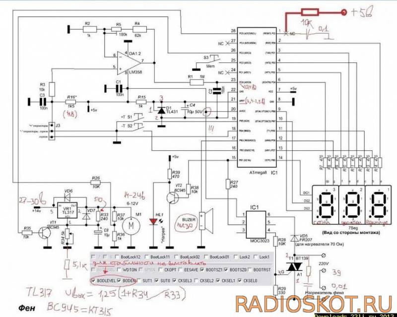
After some thought, I came to the conclusion that it is possible to connect here the same controller as on the soldering station, but with a little modification. During the operation of the soldering station, minor inconveniences were identified: the need to set the timers to 0, and sometimes an interference occurs that switches the station to the SLEEP . Considering that women do not need to remember the algorithm for switching the timer to mode 0 or 1, the circuit of the same station was repeated, but only the hair dryer channel. And minor improvements led to stable and “interference-free” operation of the thermostat in terms of control. When flashing AtMega8 firmware, you should pay attention to the new fuses. The following photo shows a K-type thermocouple, which is convenient to mount in the oven.

I liked the work of the temperature controller on the breadboard - I started final assembly on the printed circuit board.

I finished the assembly, the operation is also stable, the readings in comparison with the laboratory thermometer differ by about 1.5°C, which is basically excellent. When setting up, there is an output resistor on the printed circuit board; I have not yet found an SMD of this value in stock.

The LED models the heating elements of the oven. The only note: the need to create a reliable common ground, which in turn affects the final measurement result. The circuit requires a multi-turn tuning resistor, and secondly, pay attention to R16, it may also need to be selected, in my case it is 18 kOhm. So, here's what we have:

In the process of experimenting with the latest thermostat, more minor improvements appeared that qualitatively affected the final result, look at the photo with the inscription 543 - this means the sensor is disconnected or broken.

And finally we move from experiments to the finished design of the thermostat. I implemented the circuit into the electric stove and invited an authoritative commission to accept the work :) The only thing that my wife rejected were the small buttons on the convection control, general power supply and airflow, but this can be solved over time, but for now it looks like this.

The regulator maintains the set temperature with an accuracy of 2 degrees. This happens at the moment of heating, due to the inertia of the entire structure (the heating elements cool down, the internal frame is temperature equalized), in general, I really liked the scheme in the work, and therefore it is recommended for independent repetition. Author - GOVERNOR.
Discuss the article THERMOREGULATOR DIAGRAM
The thermostat in everyday life is used in the most different devices, starting from the refrigerator and ending with irons and soldering irons. There is probably no radio amateur who would bypass such a scheme. Most often, thermistors, transistors or diodes are used as a temperature sensor or sensor in various amateur designs. The operation of such thermostats is quite simple, the operating algorithm is primitive, and as a result, the electrical circuit is simple.
The set temperature is maintained by turning on and off the heating element (heating element): as soon as the temperature reaches the set value, the comparing device (comparator) is activated and the heating element is turned off. This regulation principle is implemented in all simple regulators. It would seem that everything is simple and clear, but this is only until it comes to practical experiments.
The most complex and time-consuming process in the manufacture of “simple” thermostats is setting to the required temperature. To determine the characteristic points of the temperature scale, it is proposed to first immerse the sensor in a vessel with melting ice (this is zero degrees Celsius), and then in boiling water (100 degrees).
After this “calibration”, by trial and error using a thermometer and voltmeter, the required response temperature is set. After such experiments, the result is not the best.
Nowadays, various companies produce many temperature sensors that are already calibrated during the production process. These are mainly sensors designed to work with microcontrollers. The information at the output of these sensors is digital and is transmitted via a single-wire, bidirectional 1-wire interface, which makes it possible to create entire networks based on such devices. In other words, it is very easy to create a multi-point thermometer to control the temperature, for example, indoors and outside the window, and not even in the same room.
Against the background of such an abundance of intelligent digital sensors, the modest device LM335 and its varieties 235, 135 look good. The first number in the marking indicates the purpose of the device: 1 corresponds to military acceptance, 2 industrial use, and three indicates the use of the component in household appliances.
By the way, the same harmonious designation system is characteristic of many imported parts, for example, operational amplifiers, comparators and many others. The domestic analogue of such designations was the marking of transistors, for example, 2T and KT. The former were intended for the military, and the latter for widespread use. But it's time to return to the already familiar LM335.
Externally, this sensor looks like a low-power transistor in a TO-92 plastic case, but inside it there are 16 transistors. This sensor can also be in the SO-8 housing, but there are no differences between them. Appearance sensor is shown in Figure 1.
Figure 1. Appearance of the LM335 sensor
According to the principle of operation, the LM335 sensor is a zener diode, whose stabilization voltage depends on temperature. When the temperature rises by one degree Kelvin, the stabilization voltage increases by 10 millivolts. A typical connection diagram is shown in Figure 2.

Figure 2. Typical LM335 sensor connection circuit
When looking at this figure, you can immediately ask what the resistance of resistor R1 is and what the supply voltage is with such a connection circuit. The answer is contained in the technical documentation, which states that normal operation The product is guaranteed in the current range of 0.45…5.00 milliamps. It should be noted that the 5 mA limit should not be exceeded, since the sensor will overheat and measure its own temperature.
What will the LM335 sensor show?
According to the documentation (Data Sheet), the sensor is calibrated on the absolute Kelvin scale. If we assume that the indoor temperature is -273.15°C, which is absolute zero Kelvin, then the sensor in question should show zero voltage. As the temperature increases by every degree, the output voltage of the zener diode will increase by as much as 10 mV or 0.010 V.
To convert the temperature from the familiar Celsius scale to the Kelvin scale, simply add 273.15. Well, everyone always forgets about 0.15, so just 273, and it turns out that 0°C is 0+273 = 273°K.
In physics textbooks, the normal temperature is 25°C, and according to Kelvin it turns out to be 25 + 273 = 298, or more precisely 298.15. It is this point that is mentioned in the datasheet as the only sensor calibration point. Thus, at a temperature of 25°C, the output of the sensor should be 298.15 * 0.010 = 2.9815V.
The operating range of the sensor is within -40...100°C and over the entire range the sensor characteristic is very linear, which makes it easy to calculate sensor readings at any temperature: first you need to convert the temperature in Celsius to degrees Kelvin. Then multiply the resulting temperature by 0.010V. The last zero in this number indicates that the voltage in Volts is indicated with an accuracy of 1 mV.
All these considerations and calculations should lead to the idea that when making a thermostat, you won’t have to calibrate anything by dipping the sensor in boiling water or melting ice. It is enough to simply calculate the voltage at the output of LM335, after which all that remains is to set this voltage as the reference voltage at the input of the comparing device (comparator).
Another reason to use LM335 in your design is its low price. You can buy it in an online store for about $1. Delivery will probably cost more. After all these theoretical considerations, we can move on to developing the electrical circuit of the thermostat. In this case, for the cellar.
Schematic diagram of a thermostat for a cellar
To design a temperature regulator for a cellar based on an analogue temperature sensor LM335, you do not need to invent anything new. It is enough to refer to the technical documentation (Data Sheet) for this component. The datasheet contains all the ways to use the sensor, including the thermostat itself.
But this diagram can be considered as a functional one, from which one can study the principle of operation. In practice, you will have to supplement it with an output device that allows you to turn on the heater of a given power and, of course, a power supply and, possibly, operation indicators. These nodes will be discussed a little later, but for now let’s see what the proprietary documentation, also known as datasheet, offers. The circuit as it is is shown in Figure 3.

Figure 3. LM335 sensor connection diagram
How does a comparator work?
The basis of the proposed circuit is the comparator LM311, also known as 211 or 111. Like all comparators, the 311 has two inputs and an output. One of the inputs (2) is direct and is marked with a + sign. The other input is inverse (3) and is marked with a minus sign. The output of the comparator is pin 7.
The logic of the comparator is quite simple. When the voltage at the direct input (2) is greater than at the inverse input (3), the output of the comparator is set to a high level. The transistor opens and connects the load. In Figure 1 this is just a heater, but this is a functional diagram. A potentiometer is connected to the direct input, setting the operating threshold of the comparator, i.e. temperature setting.
When the voltage at the inverse input is greater than at the forward input, the comparator output will go low. An LM335 temperature sensor is connected to the inverse input, so when the temperature rises (the heater is already turned on), the voltage at the inverse input will increase.
When the sensor voltage reaches the response threshold set by the potentiometer, the comparator will switch to a low level, the transistor will close and turn off the heater. Then the whole cycle will repeat.
There is absolutely nothing left - on the basis of the considered functional diagram, to develop a practical diagram, as simple as possible and accessible for repetition by beginning radio amateurs. A possible practical design is shown in Figure 4.

Figure 4.
A few explanations about the circuit diagram
It's easy to see that the basic design has changed a bit. First of all, instead of a heater, the transistor will turn on a relay, and what will turn on the relay will be discussed a little later. An electrolytic capacitor C1 also appeared, the purpose of which is to smooth out voltage ripples on the zener diode 4568. But let’s talk about the purpose of the parts in a little more detail.
The power supply of the temperature sensor and temperature setpoint voltage divider R2, R3, R4 is stabilized by a parametric stabilizer R1, 1N4568, C1 with a stabilization voltage of 6.4V. Even if the entire device is powered from a stabilized source, an additional stabilizer will not hurt.
This solution allows the entire device to be powered from a source whose voltage can be selected depending on the relay coil voltage available. Most likely it will be 12 or 24V. The power source can even be unstabilized, just a diode bridge with a capacitor. But it’s better not to skimp and put an integrated stabilizer 7812 in the power supply, which will also provide protection against short circuits.
If we're talking about relays, what can be used in this case? First of all, these are modern small-sized relays, like those used in washing machines. The appearance of the relay is shown in Figure 5.

Figure 5. Small relay
Despite their miniature size, such relays can switch currents up to 10A, which allows switching loads up to 2KW. This is if it’s all 10A, but you don’t need to do that. The most that can be turned on with such a relay is a heater with a power of no more than 1 kW, because there must be at least some “safety margin”!
It’s very good if the relay turns on the magnetic starter of the PME series with its contacts, and let it turn on the heater. This is one of the most reliable options for switching on the load. A possible implementation of this option is shown in Figure 6.

Figure 6.
Thermostat power supply
The device’s power supply is unstabilized, and since the thermostat itself (one microcircuit and one transistor) consumes virtually no power, any network adapter made in China.
If you make a power supply as shown in the diagram, then a small power transformer from a cassette recorder, calculator or something else will do. The main thing is that the voltage on the secondary winding should not exceed 12..14V. At a lower voltage the relay will not operate, and at a higher voltage it may simply burn out.
If the output voltage of the transformer is within 17...19V, then you cannot do without a stabilizer. This should not be scary, because modern integrated stabilizers have only 3 outputs, and soldering them is not so difficult.
Switching on the load
The open transistor VT1 turns on the relay K1, which, with its contact K1.1, turns on the magnetic starter K2. Magnetic starter contacts K2.1 and K2.2 connect the heater to the network. It should be noted that the heater is switched on by two contacts at once. This solution guarantees that when the starter is turned off, there will be no phase left on the load, if, of course, everything is in order.
Since the cellar is a humid, sometimes very damp room, and very dangerous in terms of electrical safety, it is best to connect the entire device using an RCD that meets all the requirements for modern wiring.
What should the heater be like?
A lot of thermostat diagrams for cellars have been published. Once upon a time they were published by the magazine “Modelist-Konstruktor” and other printed publications, but now all this abundance has migrated to the Internet. These articles give recommendations on what kind of heater should be.
Some offer ordinary 100-watt incandescent lamps, tubular heaters of the heating element brand, oil radiators (you can even use a faulty bimetallic regulator). It is also suggested to use household heaters with a built-in fan. The main thing is that there is no direct access to live parts. Therefore, old electric stoves with an open spiral and homemade “goat” type heaters should under no circumstances be used.
Check the installation first
If the device is assembled without errors from serviceable parts, then no special adjustment is required. But in any case, before turning it on for the first time, be sure to check the quality of the installation: there are no solder gaps or, conversely, closed tracks on the printed circuit board. And you must not forget to do these actions, just make it a rule. This especially applies to structures connected to the electrical network.
Setting up the thermostat
If the first switching on of the structure occurred without smoke or explosions, then the only thing that needs to be done is to set the reference voltage at the direct input of the comparator (pin 2), according to the desired temperature. To do this, you need to make several calculations.
Let's assume that the temperature in the cellar should be maintained at +2 degrees Celsius. Then we first convert it to degrees Kelvin, then multiply the resulting result by 0.010V, resulting in a reference voltage, which is also the temperature setting.
(273.15 + 2) * 0.010 = 2.7515(V)
If it is assumed that the thermostat must maintain a temperature of, for example, +4 degrees, then the following result will be obtained: (273.15 + 4) * 0.010 = 2.7715 (V)
Before installing the device, it is better to become more familiar with the principle of its operation. The Russian market offers an impressive number of models from different companies, almost all of them operate according to the same scheme, regardless of their purpose.
According to this plan, devices are made to maintain the atmosphere in an aquarium, incubator, floor, etc. It allows you to maintain thermal conditions with an accuracy of ±0.5 0 C.
The device includes a bellows for the liquid composition, a spool, a rod and an adjustable valve.
 simple thermostat circuit diagram
  thermostat diagram for incubator
 Assembly instructions
 Required materials, parts and tools:
- magnifying glass;
- pliers;
- insulating tape;
- several screwdrivers;
- copper wires;
- semiconductors;
- standard red LEDs;
- pay;
- forged textolite;
- lamps;
- Zener diode;
- thermistor;
- thyristor.
- display and internal generator with a capacity of 4 MGU (for creating digital devices on a microcontroller);
Step-by-step instruction:
- First of all, you need a corresponding microcircuit, for example, K561LA7, CD4011
- Fee must be prepared for laying tracks.
- To similar schemes Thermistors with a power of 1 kOm to 15 kOm are quite suitable, and it must be located inside the object itself.
- Heating device must be included in the resistor circuit, due to the fact that the change in power, which directly depends on the decrease in degrees, affects the transistors.
- Subsequently, such a mechanism will warm the system until the power inside the temperature sensor returns to its original value.
- Regulator sensors of a similar type need adjustment. During significant changes in the surrounding atmosphere, it is necessary to control the heating inside the object.
Assembling a digital device:
- Microcontroller should be connected together with the temperature sensor. It must have the output ports that are required to install standard LEDs that work in conjunction with the generator.
- After connecting the device to the network with a voltage of 220V, the LEDs will automatically turn on. This will indicate that the device is in working condition.
- The microcontroller design contains memory. If the device settings are lost, the memory automatically returns them to the originally specified parameters.
When assembling the structure, we must not forget about safety precautions. When using a temperature sensor in a watery or humid atmosphere, its terminals must be hermetically sealed. The value of thermistor R5 can be indicated from 10 to 51 kOhm. In this case, the resistance of resistor R5 must have a similar value.
Instead of the designated K140UD6 microcircuits, you can use K140UD7, K140UD8, K140UD12, K153UD2. Any instrument with a stabilization power of 11…13 V can be used as a zener diode VD1.
In the case when the heater exceeds the voltage of 100 W, then VD3-VD6 must be superior in power (for example, KD246 or their analogs, with a reverse power of at least 400V), and the thyristor must be mounted on small radiators.
The value of FU1 should also be made larger. Controlling the device comes down to selecting resistors R2, R6 in order to safely close and open the SCR.
Device
 mechanical thermostat circuit diagram
 The temperature always remains at the same level by turning the heating device (heating element) on and off. Similar principle control is used on all simple structures.
It may seem that the thermostat circuit is very simple, but as soon as it comes to assembling the device, a lot of questions arise related to the technical part.
The thermostat device includes:
- Temperature sensor– created on the basis of the DD1 comparator.
- Key circuit of the thermostat is the comparator DA1, made on an operational amplifier.
- Required temperature indicator is set by resistor R2, which is connected to inverting input 2 of the DA1 board.
- As a temperature sensor Thermistor R5 (type MMT-4) appears, connected to the input of the 3rd device.
- Design diagram has no galvanic isolation from the network, and takes energy from the parametric stabilizer on parts R10, VD1.
- As a power supply for the device You can take a cheap network adapter. When connecting it, you must be guided by the rules and requirements for new wiring, since the room conditions can be electrically hazardous.
A small supply of capacitor C1 contributes to a gradual increase in power, which leads to a smooth (no more than 2 seconds) switching on of electric lamps.
Self-assembly costs
 Today, any such gadget can be purchased in a store. The price range is quite wide, and the cost of many models is over 1000 rubles. In terms of financial investments, this is quite unprofitable, so it is much cheaper to do it yourself.
Costs for self-assembly are several times lower, namely:
- K561LA7 board will cost no more than 50 rubles;
- thermistor with a power of 1 kOm to 15 kOm - about 5 rubles;
- LED (2 pcs) – 10 rub.;
- Zener diode - 50 rubles;
- thyristor - 20 rubles;
- display – 200 rubles (for creating digital devices on a microcontroller);
The purchase of lamps, foil and other materials will cost no more than 100 rubles. It turns out that the cost of self-assembly will have to be spent no more than 430 rubles and a little personal time. The owner can completely adapt the device to his needs, using a simple circuit for this.
Operating principle

The thermostat circuit is multifunctional. Starting from its foundation, you can create any adapted device that will be as convenient and simple as possible. The supply power is selected in accordance with the available relay coil voltage.
The principle of operation of the adjusting device is the ability of gases and liquids to compress or expand during cooling or heating. Therefore, the operation of water and gas configurations is based on the same essence.
They differ from each other only in the speed of reaction to changes in temperature in the house.
The principle of operation of the device is based on the following stages:
- As a result of changes in the temperature of the heated object, there is a change in the operation of the coolant in the heating mechanism.
- Together with that, this causes the siphon to increase or decrease its dimensions.
- After that, there is a displacement of the spool, which balances the coolant inlet.
- Siphon interior filled with gas, facilitating uniform temperature regulation. The built-in temperature sensor monitors the external temperature.
- Each heat level value the specific value of the pressure force of the working atmosphere inside the siphon is equated. The missing pressure is compensated by a spring that controls the operation of the rod.
- As a result of increasing degrees the valve cone begins to move towards closing until the operating pressure level in the siphon becomes balanced due to the forces of the spring.
- If the degrees drop, The work of the spring is reversed.
The result of the work depends on the type and functionality of the control valve, which is directly subordinate to the heating circuit and the diameter of the supply pipe.
Kinds

Manufacturing companies offer customers 3 types of thermostats, each of which has different internal signals. They control the heating process of the coolant and equalize the temperature order.
Signal expansion methods:
- Directly from the coolant. It is considered insufficiently effective, so it is used infrequently. Its operation is based on an immersion sensor or similar mechanisms. Compared to other types, it is one of the most expensive.
- Internal air waves. It is the most reliable and economical option. It balances the air during its changes, and not the level of water heating. Easy to install in an apartment. It communicates with heating communications using a cable through which the signal is transmitted. Thermostats of this type are constantly being updated with new functions and are quite convenient to use.
- External air waves. High efficiency is achieved by providing an immediate response to any weather changes. Signs in the form of a signal sent by the diaphragm give the system a command to open or close the pipe with the heating device.
In addition, the devices can be electrical and electronic.
According to the scheme and option for receiving a signal, devices are divided into semi-automatic and automatic, which, in turn, can:
- Control heating level of the radiator and line branch.
- Track according to the boiler power.
Review of thermostats on the market
 Thermostat IWarm 710
 The most popular models today include the E 51.716 and IWarm 710. Their non-flammable body made of plastic polymer is small in size, but has a large number of useful tasks and a built-in battery. It has a fairly large built-in display that displays the corresponding temperature characteristics.
The cost of these models is presented in the range of 2,700 thousand rubles.
The features of E 51.716 include the fact that it has a 3 m long cable, is capable of balancing the temperature simultaneously from the floor itself, and that the device can be built into the wall in any position.
The only thing you should think about before installing it is how exactly it will be located so that the switch buttons are not covered by foreign objects and are easily accessible.
The disadvantages of the thermostat include an insignificant set of functions, however, similar devices perform them quite easily. This may cause discomfort during operation. Also, the memory of the E 51.716 and IWarm 710 does not have an automatic heating function, so you will have to do this yourself.
Electronic regulators with a mechanical operating principle:
- Regulation of work based on automation, and carried out using buttons located on the panel.
- Includes display, which indicates the previous and specified degrees.
- It is possible to configure the device yourself: number, operating time, heating cycle with maintaining a specific mode, you can also specify the degree of heating.
- Compared to mechanical analogues, the temperature of electric models is easily adjusted by approximately 0.5 values.
The purchase of such a model will cost no more than 4 thousand.
Electronic components:
- Independently control the temperature.
- Just one device can control the atmosphere several days in advance and separately for each room.
- Allows you to set the “absence” mode, and don’t spend extra money on it if no one is at home.
- The system automatically analyzes the quality of work devices in every room. The owner will not have to guess about possible malfunctions in the operation, since the system will identify all the defects on its own.
- Manufacturers of expensive models provided the ability to control modes while away from home. Adjustment is carried out using the built-in Wi-Fi router.
The cost of such devices depends on the set of built-in functions, so it varies from 6,000 to 10,000 thousand rubles and more.
Thermostats are widely used for various purposes: in cars, heating systems of various types, refrigerators and furnaces. Their job is to turn off or turn on devices after reaching a certain temperature. It’s not difficult to make a simple mechanical thermostat with your own hands. Modern designs have a more complex design, but with some experience it is possible to make analogues of such structures.
- return spring;
- two levers;
- two aluminum tubes;
- adjusting unit (looks like a crane axle box);
- a chain that connects two parts (thermostat and door).
- threshold circuit;
- indicator device;
- temperature sensor.
- thermistors;
- semiconductor elements;
- resistance thermometers;
- bimetallic relays;
- thermocouples.
- power transistor;
- potentiometer;
- a thermistor that will act as a temperature sensor.
- 1. Data is taken directly from the coolant. It is not very popular in everyday life, since its effectiveness is insufficient. The operating principle is based on an immersion sensor or other similar device. Although there are problems with efficiency, it belongs to the expensive segment of such devices on the market.
- 2. Internal air waves. This option is the most popular because it is considered reliable and economical. It takes data not from the temperature of the coolant, but directly from the air. This allows for higher accuracy. What degree will be set in the control unit will be the air temperature. Connects to the heating system using a cable. Such models are constantly being improved by manufacturers, which makes them more convenient and functional.
- 3. External air waves. Operates on the basis of a street sensor. It is triggered by any changes in weather conditions and reacts immediately by changing the settings of the heating equipment.
Show all
Mechanical thermostat

 Today, the newest models of thermostats are controlled using touch buttons, older models - mechanical. Most of these devices have a digital panel that displays the temperature of the coolant in real time, as well as the required maximum degree.
The production of such devices is not complete without programming them, so their price is very high. They allow you to customize temperature regime By different parameters, for example, by hour or day of the week. The temperature will change automatically.
If we talk about thermostats for industrial steel furnaces, it will be difficult to make them yourself, since they have a complex design and require the attention of more than one specialist. These are mostly made in factories. But making a simple temperature controller with your own hands for an autonomous heating system, incubators, etc. is not a difficult task. The main thing is to adhere to all drawings and production recommendations.
In order to understand how the thermostat works, you can disassemble a simple mechanical structure. It works on the principle of opening and closing the door (damper) of the boiler, thereby reducing or increasing the access of air to the combustion chamber. The sensor reacts, of course, to temperature.
To produce such a device you will need the following components:
All components must be assembled and mounted on the boiler.
The device works thanks to the property of aluminum to expand under the influence of temperature. In this regard, the damper closes. If the temperature decreases, the aluminum pipe cools and decreases in size, so the damper opens slightly.
But this scheme also has its significant disadvantages. The problem is that it is difficult to determine when the damper will operate this way. To approximately adjust the mechanism, precise calculations are needed. It is impossible to determine exactly how much an aluminum pipe will expand. Therefore, in most cases, devices with electronic sensors are now preferred.
Homemade mechanical thermostat for a mine boiler


Simple electronic device
For more accurate operation of an automatic temperature controller, you cannot do without electronic components. The simplest thermostats operate using a relay-based circuit.


The main elements of such a device are:
The homemade thermostat circuit must respond to an increase (decrease) in temperature and turn on the actuator or suspend its operation. To implement the simplest circuit, bipolar transistors should be used. The thermal relay is made according to the Schmidt trigger type. The thermistor will act as a temperature sensor. It will change resistance depending on the temperature, which is adjusted in the general control unit.
But in addition to a thermistor, a temperature sensor can be:
When using diagrams and drawings from unknown sources, it is worth keeping in mind that they often do not correspond to the attached description. In this regard, it is necessary to carefully study all the material before proceeding with the manufacture of the device.
Before starting work, you need to decide on the temperature range of the device, as well as its power. It must be taken into account that some components will be used for the refrigerator, and others for heating equipment.


A device consisting of three components

 A simple DIY electronic thermostat can be assembled for use on fans and personal computers. Thus, you can understand the principle of its operation. A breadboard is used as the basis.
The tools you will need are a soldering iron, but if you don’t have one or don’t have enough experience, you can also use a solderless board.
The scheme consists of three elements:
The temperature sensor (thermistor) reacts to an increase in degrees, and therefore the fan will turn on.
To adjust the device, you must first set the data for the fan to the off position. Then you need to turn on the computer and wait until it warms up to a certain temperature in order to record the moment the fan turns on. The setup is done several times. This will ensure the effectiveness of the work.
Today, modern manufacturers of various elements and microcircuits can offer a large selection of spare parts. They all differ in technical specifications and appearance.
DIY thermostat


Temperature controllers for heating systems
When making and installing a thermostat with an air temperature sensor with your own hands for heating systems, it is necessary to accurately calibrate the upper and lower lines. This will avoid overheating of the equipment, which can lead to failure of the entire system at best. At worst, overheating equipment can cause it to explode and possibly be fatal.


For these purposes, you will need a device to measure current strength. Using drawings and diagrams, you can make external equipment for adjusting the temperature of a solid fuel boiler. For work, you can use the K561LA7 circuit. The principle of operation lies in the same ability of a thermistor to reduce or increase resistance under certain temperature conditions. The desired parameters can be set using an AC resistor. First, the voltage is supplied to the inverter, and then transmitted to the capacitors, which are connected to the triggers and control their operation.
The principle of operation is simple. As the degrees drop, the voltage in the relay increases. If the value is less than the lower limits, the fan automatically turns off.
It is better to solder the elements on a mole rat. As a power supply, you can use a device that operates within 3-15 V.
Any homemade device installed on the heating system can lead to its failure. In addition, such actions may be prohibited by government control services. For example, if a gas boiler is installed in the house, then such additional equipment may be removed by the gas service. In some cases, fines are even issued.
Do-it-yourself thermostat for heating elements: diagram and instructions
Digital equipment

 To manufacture a modern device with precise adjustment of the required degrees, you cannot do without digital components.
The main chip is PIC16F628A. With this scheme you can control various devices electronic type.
The operating principle is also not very complicated. The values of the set (required) temperature and the current temperature are supplied to a three-charge indicator with a common cathode.
To set the desired temperature, the microcircuit has two elements sb1 and sb2, to which mechanical buttons are subsequently soldered. The first element serves to reduce the temperature, and the second to increase it.
Setting the hysteresis value is performed by simultaneously pressing the sb3 button when setting.
When making homemade devices, it is important not only to solder and manufacture the circuit correctly, but also to place the device on the equipment in the right place. The board itself must be protected from moisture and dust to avoid the appearance of short circuit, and accordingly failure of the device. Isolation of all contacts also plays a very important role.
Thermostats
Types of devices on the market
Today, companies that produce such equipment offer the buyer 3 main types of devices. They all operate on different internal signals. Their function is to control the temperature and equalize it depending on the device settings (upper and lower lines).


There are three types of internal signals:
Such devices can be either electrical or electronic. Thermostats can receive signals in automatic or semi-automatic mode. Operation and temperature changes can occur by monitoring the temperature of radiators and main lines or by recording changes in boiler power.
Today on the market there is many popular models from top manufacturers who have already secured their position. These primarily include E 51.716 and IWarm 710. The body itself is small in size and made of plastic polymer, which does not burn. Despite this, it has many useful functions. The display is quite large for such small sizes. It displays all existing data. Such devices cost between 2500-3000 rubles.

 The functional features of the first model include the ability to mount it into a wall in any position, the temperature is controlled simultaneously from the floor itself, as well as the presence of a 3 m long cable. During installation, you need to think about whether there will be free access to the device for unhindered control.
To the above advantages, you can add some disadvantages. These include a small set of functions that are found in analogues of these devices. This sometimes causes discomfort when used. In addition, these models do not have an automatic heating function. But if you wish, you can finish it yourself.
Thus, making a thermostat yourself or purchasing and installing a ready-made model will not be difficult if you strictly adhere to all diagrams, drawings and instructions for manufacturing and installation. This equipment will save owners time on manually adjusting the temperature of certain devices.


