Electronic on-off timer. Multifunctional cyclic timer Description of the operation circuit of a simple digital timer
Cyclic timer Minute-1 designed to switch loads with adjustable intervals of on and off states from 1 second to 99 hours. The set values of time intervals are written to the non-volatile FLASH memory of the device and are therefore saved when the power is turned off. If the user has set the on and off intervals - timer on the microcontroller Minute-1 works in cyclic mode, i.e. The output relay alternately turns the load on and off. If the user has set only the on interval and the off interval has not been set - digital timer Minute-1 operates in single counting mode, i.e. At the end of the set time, the output is reset and the countdown stops. The advantage of a cyclic timer is that the countdown begins immediately after the device is turned on.
Technical characteristics of the cyclic timer Minute-1| Parameter | Meaning |
| Upit. constant, V | +11...15 |
| Upit. nom. constant, V | +12 |
| Iconsumption Max. at Upit. nom., mA | ...50 |
| Recommended power supply not included | Rodnik-12V/2A, PW1215B, ES18E12-P1J, GS15E-3P1J, GS25E12-P1J |
| On Interval | 1 sec... 99 hour |
| Off interval | 1 sec... 99 hour |
| Number of TTL outputs | 4 |
| Number of relay outputs | 1 |
| Output load capacity | 10 A / +24 V 10 A / ~220 V |
| Type of relay used | BS-115C-12A-12VDC |
| Suitable for | Cyclic load switching One-time counting of the set interval On delay |
| Overall dimensions, LxWxH, mm | 80 x 47 x 10 |
| Recommended housing, not included | BOX-KC01 Shell-85x50x21 |
| Operating temperature, °C | 0...+55 |
| Relative operating humidity, % | ...55 |
| Production | Contract manufacturing in Russia |
| Warranty period | 12 months from date of purchase |
| Weight, g | 100 |
 Description of the timer on the Minutka-1 microcontroller
The main element of the cyclic timer is the STM32F100RBT6B microcontroller, which switches the output in accordance with the set on and off time values and displays the timer time on the indicator. The countdown time is displayed in two modes: "Minutes: Seconds" and "Hours: Minutes". The display mode is selected by the SELECT button on the right, when pressed, the display alternates between “SECO” (Minutes: Seconds mode) and “hour” (Hours: Minutes mode).
Option for installing a cyclic timer Minute-1 in the BOX-KC01 housing (not included) Setting the time for the on and off states of the digital timer Minute-1
Set the time for the on and off states of the output for which:
- Log in display mode "Hours: Minutes", to do this, press the SELECT button several times until "hour" is displayed on the display ("Hours: Minutes" mode).
- Press and hold the LESS button on the left. In this case, no changes occur on the display.
- Press the SELECT button on the right while pressing the LESS button on the left. In this case, “-on-” is briefly displayed on the display, which corresponds to the installation mode time seconds on state and then “SECO” (setting on seconds) is displayed briefly. Entering the mode is easy to notice, because In this case, the display shows two digits instead of four and the dividing dot flashes.
- Set the required on-time seconds value using the LESS buttons on the left and MORE buttons in the middle.
time minutes on state. In this case, “ninu” is briefly displayed on the display, which corresponds to setting the minutes of the on state.
- Press the SELECT button on the right to go to installation ON clock time. In this case, “hour” is briefly displayed on the display, which corresponds to the setting of the on-state clock.
Press the SELECT button on the right to go to installation. In this case, “-OFF” is briefly displayed on the display, which corresponds to the installation mode time seconds off state and then "SECO" is displayed briefly, which corresponds to the setting of the seconds of the off state.
- Set the required seconds value using the LESS buttons on the left and MORE buttons in the middle.
- Press the SELECT button on the right to go to installation time minutes off state. In this case, “ninu” is briefly displayed on the display, which corresponds to the setting of the minutes of the off state.
- Set the required minute value using the LESS buttons on the left and MORE buttons in the middle.
- Press the SELECT button on the right to go to installation OFF clock time. In this case, “hour” is briefly displayed on the display, which corresponds to the setting of the clock in the off state.
- Set the required hour value using the LESS buttons on the left and MORE buttons in the middle.
Press the SELECT button on the right to exit setup mode. In this case, “SAFE” is briefly displayed on the display (if any of the values have been changed) and the set values are written to the internal non-volatile FLASH memory of the device. The display then briefly shows "SECO" (Minutes: Seconds mode), after which the countdown time is displayed.
- Setting the on and off times of the output is completed.
Sometimes a situation arises when cyclic switching of the output is not required and it is quite enough to execute only one timer period. In this case, please set only the on-state interval (the off-state interval is equal to zero) - and the timer on the MINUTKA-1 microcontroller will count only one interval and stop. The single sample mode is easy to notice because the dividing dot on the display flashes. At the end of the count, "StOP" appears on the display.
Connection diagram of the cyclic timer Minute-1 Electrical circuit diagram of a timer on the Minutka-1 microcontroller
 Demonstration of the cyclic timer Minute-1
Purpose of contacts and indication elements of the cyclic timer Minute-1
Demonstration of the cyclic timer Minute-1
Purpose of contacts and indication elements of the cyclic timer Minute-1 correspond to the Minutka-4 timer (both timers have the same firmware)
 Frequently asked questions about the Minute-1 timer
- Can the Minute-1 timer switch a DC load?
- Yes, the Minutka-1 timer can switch both AC and DC loads thanks to the use of a “dry changeover contact” relay at the output (the output is galvanically isolated from the circuit).
Is it possible to add additional LEDs to the Minutka-1 board and install a jumper to obtain the Minutka-4 functionality (get 4 timers)?
- Yes, sure. All Minutka series devices have the same firmware and, by adding the necessary elements to the board, they receive all the capabilities of a more functional device.
The timer is designed to turn on the load for a specified time interval once every 24 hours. The range of possible timer intervals is from 1 hour to 23 hours, the minimum discreteness of the setting step is 1 hour.
Thus, the timer can turn on the load for a specified time once a day.
The device can be used in practical applications to turn on ventilation, lighting in a greenhouse or circulation of a water pump for a certain time during the day in an endless cycle, or, for example, to control an aquarium compressor: turn it off at night to keep it quiet, and turn it on during the day.
The schematic diagram of the timer is shown in the figure below.

The details used are common. As a relay K1 Any relay with a supply voltage of 12 volts and a load switching current of at least 1 A is suitable. Transistor VT1- bipolar NPN structure, medium power, you can use domestic analogues KT315, KT503. Microcontroller - AVR family ATtiny13. In the project, the clock frequency of the internal oscillator of the microcontroller is selected = 1.2 Mhz (9.6/8). How to set fuses for two popular programmers ( Chip Blaster And PonyProg) when programming the chip is shown in the pictures below.


After assembly, you need to program the timer time. The user must enter the operating time of the external device into the non-volatile memory of the microcontroller using the buttons. This is the time that will determine the duration of operation of the device being turned on. This is done once, all subsequent work cycles will adhere to these settings until you need to change them to others in the same way.
The sequence for setting the timer time is as follows.
Turn on the power HL2 is constantly on and HL1 flashes approximately once every 10 seconds (if this does not happen, you need to check the correct assembly and firmware of the MK). Now simultaneously press and hold down both the “SET” and “RESET” buttons - HL2 goes out. Release the "RESET" button first, and leave the "SET" button pressed - HL1 starts flashing at a frequency of 1 time per second. We count the required number of LED flashes HL1(one flash means 1 hour exposure) and release the “SET” button. This is how you enter the required number of hours of work.
After releasing the "SET" button to check the correctness of the interval entry HL1 will blink as many times as it was set (if a number greater than 23 was set by mistake, the indicator will blink 23 times). After this the indicator HL1 lights up for 5 seconds and goes out - this means that the timer has been set and the working cycle has begun. Now this indicator HL1 will flicker once every 10 seconds indicating that the circuit is in operation.
Second indicator HL2 will be constantly lit during the specified active time of the timer, and will be extinguished during the pause period. The graph below shows how the timer works.

In the appendix to the article there are 2 archives: one contains the timer firmware, a diagram in Splan7 format and a short text description, and the second contains the project Proteus with modified firmware to familiarize yourself with the principle of operation of the timer. The modification of the firmware is that the timer's operation is accelerated - it runs in minutes instead of hours. Those. if you set the operating mode to "8 hours on, 16 hours off", when simulating in Proteus With normal firmware you will have to wait all 8 hours until the shutdown occurs, but with accelerated firmware you will have to wait only 8 minutes. Accordingly, the period of accelerated firmware is not 24 hours, but 24 minutes.
And turn off again. Almost like a refrigerator, only the frequency of the refrigerator depends on the temperature, and we need to set the necessary time intervals ourselves.
Let's consider a circuit of an electronic timer in which the cyclicity of work and “rest” can be set separately. The time is set by variable resistors, in the range from 90 seconds to 3 hours, separately for each mode. The values of the specified intervals completely depend on the parameters of the RC circuits, with variable resistors in the “R” components. In this regard, this electronic timer does not have very high accuracy.
The circuit consists of a timer unit on a K561IE16 binary counter (analogous to 4020), which differs from the “standard” one in that it has two adjustable multivibrators. By setting the frequency of one, you set the duration of the on state, and by setting the frequency of the other, you set the duration of the off state. Multivibrators are switched by a transistor-diode circuit depending on the logical level at the high output of the counter. The same counter output is used to control the load.
In the initial state (after turning on the power with switch SB1), counter DD2 is set to zero by a jump in the charging current of capacitor C2. Its output (pin 3) will be logical zero. Transistor VT2 opens, transistor VT3 also opens and relay K1 closes its contacts, the output of the circuit is connected to the open circuit of the power supply of the electrical device that needs to be controlled. That is, practically parallel to the switch of this electrical appliance.
At the same time, zero from pin 3 of DD2 goes to pin 9 of DD1.4 and to the base of VT1. In this case, VT1 is closed, there is a high voltage level on its collector, which comes to pin 6 of DD1.2. It turns out that the multivibrator assembled on elements DD1.3-DD1.4 works, pulses from its output pass through the diode VD1 to the counting input DD2. But the multivibrator on elements DD1.1-DD1.2 does not work, its output is zero. But this does not affect the passage of pulses to the counter from the second multivibrator, since the diode VD2 is closed and does not affect the counter input.
Thus, the period when the electrical appliance is turned on begins. This will continue until counter DD2 reaches the 8192nd pulse. That is, until a unit appears at its pin 3. How long this will take depends on the resistance R7.
When a one appears on pin 3 of DD2, the interval of the electrical device’s on state ends and a pause begins. Transistors VT2-VT3 close and relay K1 turns off the electrical appliance. And transistor VT1 opens. A one from output DD2 passes to pin 9 of DD1.4, so the multivibrator DD1.3-DD1.4 is turned off. At the VT1 collector, the voltage drops to zero. This corresponds to the voltage at pin 6 of DD1.2. Therefore, the multivibrator DD1.1-DD1.2 is turned on. Pulses from its output through diode VD2 are supplied to input “C” of counter DD2. From this moment the countdown of the pause interval begins. LED HL1 indicates the on state of relay K1.
Any network adapter with a rated output voltage of 9-15V and a current of at least 150 mA is suitable as a power source.
Using the SC1240 relay, you can switch the load at a 220V AC mains voltage with a power of no more than 2 kW. If this is not available, you can use a domestic relay, but you should give preference to those relays that are in a plastic case, since a similar relay in a metal case will not be able to operate safely on 220V alternating voltage. In addition, it is advisable to use specialized relays whose contacts and design are primarily designed for switching AC mains voltage.
Instead of a relay, you can use some kind of optothyristor or posisimistor circuit. In this case, transistor VT3 and, accordingly, relay K1 are excluded from the circuit. And the optocoupler LED is connected instead of resistor R13. In this case, resistance R10 must be selected according to the current that should flow through the optocoupler LED.
The advantage of the relay is that it is, in fact, an ordinary mechanical switch, that is, a linear device like a piece of wire, and does not introduce any distortions or additions (such as emissions at each half-cycle) into the sinusoid of alternating voltage from the network. Therefore, it is still better to power electrical appliances with electronic components through a relay. But the disadvantage of the relay is obvious - mechanical contacts, sparking, burning, in general, mechanics, which in themselves are not as reliable as a thyristor or triac. Therefore, if you need to control a powerful heating element, or some other electrical device without built-in electronics, then it is better to use an optosimistor.
When selecting a time relay for “one craft,” several different modifications were purchased. In the review, a variant of a cyclic time relay
It all started with a search for a relay with a certain type of operation (according to the PS code - FE mode was required). It will probably be unnecessary to go into the details of this mode of operation in this review (later there will be a more interesting review with details of the types and the constructed device), so I’ll skip a little further...
During the search process, I realized that it is almost impossible to get from sellers diagrams of relay operation or even a simple answer to the question WHETHER IT WILL WORK in a given mode. Therefore, several trial orders of various relay modifications were made in order to test their capabilities and try to assemble the device I needed from them. Below is a description of one of the purchased samples. This is an option cyclic switching relay conditions during the entire time of power supply. Options for using all kinds of switching on thermostats, lighting, etc.
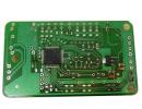
Appearance of the relay and its dimensions 
Assembled on STC15W202S, convenient terminal blocks for wires are installed for integration into circuits. 
sizes... 

The quality of soldering is average - there are voids, and in general the impression of “dry soldering” with an insufficient amount of flux. 
First of all, the functionality of the device was checked. 
In principle, everything is fine, I had to figure out the controls a little, below I will describe the functions and purpose of the buttons.
There are two buttons labeled K1 and K2.
In the initial position, K1 enters the settings and K2 switches the delay time range, there are several options selected cyclically in a circle - 99.9 sec, 999 sec, 9999 sec. Those. You can select from 0.1 sec to 9999 sec for both the on and off time of the relay.
When entering the settings mode (pressing K1 once), the K1 button begins to perform the function of “entering” and selecting mode settings (on or off relay state) and the K2 button scrolls through values. In short, everything is extremely simple and easy to understand.
This relay code PS refers to LI (Asymmetric cycle repeat (initial pulse ON))
Power is supplied to the timer. The output contacts operate immediately and switch between ON and OFF positions as long as power is supplied. The dwell time in the closed (Ta) and open (Tr) states is independently adjustable.
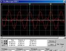
Diagram of operation of this relay  Ta and Tr as I wrote above, it is possible to adjust from 0.1 sec to 9999 sec.
When the relay is operating, the indicator constantly contains indications of the remaining time before changing the operating mode and an indication of operation (blue LED) and 12V power supply (red LED). The relay has a normally closed and normally open contact with a stated switching current of up to 10A.
Below is a short video of the work.
Cons: soldering, lack of instructions and operation diagrams.
Pros - A fully functional cyclic relay with a reasonable price tag. It can be recommended for use in various automation systems using its capabilities. Convenient terminal blocks for connecting to circuits. Relatively large switched load current. Possibility of switching with power supply isolation. I'm planning to buy +40 Add to favorites I liked the review +38 +68
Timer is a device for controlling actuators and loads according to time cycles. This is an improved and more feature-rich final version of the previously published circuit:
Multifunctionality is as follows: four functions are implemented programmatically in one device.
- cyclic timer with the ability to work in two configured time periods indefinitely.
- timer function, work in two configured time periods once.
- countdown timer.
- stopwatch
- autorun can be configured from the menu in two options:
1) option, after supplying 5V power to the MK circuit, the countdown begins immediately
2) option, after supplying 5V power to the MK circuit, the countdown will begin only after pressing the ▲ start button.
The data of the selected mode of one of the four (cyclic timer, cycle timer once, countdown timer, stopwatch, autorun state) is saved in the non-volatile memory of the MK automatically, and after the next 5V power supply to the MK circuit is restored automatically.
Recording of time segments of timer No. 1 and timer No. 2 are recorded in the non-volatile memory of the MK in the active state of the timer (see menu description) and with each new 5V power supply to the MK circuit, the previously recorded values are restored automatically.
Timer characteristics:
- cyclic timer two independent adjustable time ranges: timer No. 1 from 1 second to 96 hours (four days) and timer No. 2 time period from 1 second to 99 minutes.
- timer function, work in two configured time periods once. Ranges, timer No. 1 from 1 sec to 96 hours and timer No. 2 from 1 sec to 99 minutes. Graphically:
- countdown timer, with time intervals ranging from 1 second to 96 hours.
- stopwatch from 1 second to 24 hours, and then in hourly mode from 0 seconds.
Multifunctional cyclic timer circuit:

Control:
In the main screen mode, the ▲▼◄ buttons quickly control the following:
▲ start, pause;
▼ reset
enter menu
◄ return
By simultaneously pressing the ◄ ▲ buttons, the temporary data displayed on the screen is recorded into the non-volatile memory of the MK.
By simultaneously pressing the ◄ ▼ buttons, temporary data located in the non-volatile memory of the MK is read and displayed on the LCD screen.
Menu system:
All functions are controlled using 4 buttons, conventionally designated by symbols:
▲▼◄ Menu navigation can be done easily using hints.
A hint is a symbol ▲▼◄ that corresponds to a specific button.
To switch from the main mode to the menu system, press the menu button.
The menu is completely Russified and the displayed tips in the form of ▲▼◄ symbols will be your tips in this navigation.
Graphically, menu navigation looks like this:

If after a while you forget what interval you have programmed in the MK’s memory, you can go to the menu, the “set time” item displays the previously recorded time values.
And also, if you enter any menu item and do not press any button for 30 seconds, you will return to the main mode automatically.
All information about active states is displayed on the LCD.
Description of operating modes
- cyclic timer with the ability to work in two configured time periods indefinitely.
Two timers take part in the work cycle. On the LCD screen timers are indicated as t No. 1 And t No. 2
Visually, the operation of a cyclic timer can be displayed with the following graph.

For the operation of cycles, the time is set with an accuracy of a second;
counting range: timer No. 1 from 1 sec to 96 hours and timer No. 2 from 1 sec to 99 minutes.
After setting the required time intervals, you need to save these values into the memory of the MK (in the menu corresponding to the timer, using the save button, or in the main screen mode, simultaneously using the ◄ ▲ buttons.
In the main mode, by pressing the start button, timer No. 1 will begin counting.
When the value reaches 00:00.00, the actuator is turned on, and timer No. 2 continues counting (at this time, the readings of timer No. 1, reset to 00:00.00, will be restored automatically in accordance with the data of the non-volatile memory of the MK).
And also if timer No. 1 is in the ten second interval before the load is turned on, the buzzer will sound several times ((PC5) 28 MK leg).
Timer No. 2, when the value reaches 00.00, the actuator turns off, and timer No. 1 continues counting (at this time, the readings of timer No. 2, reset to 00.00, will be restored automatically in accordance with the data of the non-volatile memory of the MK).
And this will continue endlessly...
While the cyclic timer is running, you can quickly control the operation of the timers using the buttons
▲ pause button, the countdown will stop. (The state of activity (PC0) 23 leg of the MK will not change) double pressing the pause button leads to the resumption of the stopped count.
Button ▼ reset, the countdown will stop, the readings on the LCD screen will be reset to zero (but not in the non-volatile memory of the MK) and if the actuator was turned on, it will turn OFF.
Display of symbols on the LCD > +< означает, что при однократном нажатии кнопки старт начнется (продолжится) отсчет времени таймеров №1 или №2.
Also, if there is a short-term power loss in the network (or we simply disconnect the timer from the network for a long period), then when voltage appears, the device will save its settings and if the autostart function was enabled, the timer will turn on again and continue to operate in a closed cycle.
Function timer one cycle, will operate in two configured time periods once.

Controls and settings will be as described above.
Timer #1 starts counting down.
When the value reaches 00:00.00, the actuator is turned on, and timer No. 2 continues counting (at this time, the readings of timer No. 1, reset to 00:00.00, will be restored automatically in accordance with the data of the non-volatile memory of the MK).
Timer No. 2, when the value reaches 00.00, turns off the actuator,
The actuator is disabled and the countdown does not resume until the start button ▲ is pressed.
The autorun function works similarly here.
If this function is not activated, after power is applied to the timer circuit, the timer will wait until you press the start button ▲.
If, through the user menu, the autorun function was activated, after power is supplied to the timer circuit, the timer will turn on again and start working according to the previously recorded values in the MK memory.
The timer will operate once; at the end of the countdown, the actuator will turn off.
- countdown timer

Here the principle of managing and using the autorun function is practically no different.
But still they exist. Only timer No. 1 takes part in the work.
When the value 00:00.00 is reached, the actuator is turned on and the countdown stops.
The actuator will be turned on until the ▼ reset button is pressed.
- stopwatch
It is controlled by the start ▲ pause, ▼ reset buttons. The stopwatch operates based on a 24-hour cycle display format.
List of radioelements
| Designation | Type | Denomination | Quantity | Note | Shop | My notepad |
|---|---|---|---|---|---|---|
| MK AVR 8-bit | ATmega8 | 1 | To notepad | |||
| Linear regulator | LM78L05 | 1 | To notepad | |||
| Bipolar transistor | BC547 | 1 | To notepad | |||
| Rectifier diode | 1N4148 | 1 | To notepad | |||
| LCD display | LCD 16x2 | 1 | To notepad | |||
| 470 µF | 1 | To notepad | ||||
| Electrolytic capacitor | 100 µF | 1 | To notepad | |||
| Electrolytic capacitor | 1 µF | 1 | To notepad | |||
| Capacitor | 0.1 µF | 1 | To notepad | |||
| Trimmer resistor | 5 kOhm | 1 |