Multisim library elements. Creating circuits in the multisim program Multisim how to connect power
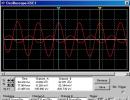
For example, consider an amplifier stage based on a bipolar transistor - connected to a circuit with a common emitter. Let's plot the dependence of the output and input voltages on time, the transfer characteristic, the amplitude-frequency and phase-frequency characteristics.
1) Let's assemble the circuit under study in the Multisim environment
Note:
- double-clicking the left mouse button on an element allows you to change its parameters
-for convenience when working, you can change the color of the wires (select the wire with the right mouse button and select Change Color in the context menu that appears)
2) We launch the circuit, the oscilloscope automatically builds graphs of the dependence of the input and output voltages on time (in order to view them, just left-click on the oscilloscope).
In the active Oscilloscope-XSC1 window, you can zoom in and out, shift the graphs along the ordinate and abscissa axes, use the cursor to view the parameters at each point of the graph (here, the voltage value), using the Save button you can save the oscilloscope data in the form of a table in a text file .

3) Construction of similar graphs using Transient Analysis.
Using the plotter button to display cursors and data, you can see the voltage value at any point. During analysis, graphs are displayed in different colors for convenience.
In the Transient Analysis window, on the Output tab, select the quantities necessary for analysis, and on the Analysis Parameters tab, you can set the start and end times of the analysis (the same actions are performed in any type of analysis).

4) Construction of the transfer characteristic (dependence of the output voltage on the input) using DC-Sweep Analysis. Working with a graph in a plotter (Grapher View) is done in the same way.

5) Construction of frequency response and phase response (using AC-Analysis).
With this article I begin to cover one of the most interesting topics - the topic of computers, they also say circuit modeling of circuits of various electronic devices.
In general, the term modeling of electronic circuits has many synonyms, including emulation of electronic circuits, simulation of electronic circuits, etc. I will stick to the term “computer modeling” or modeling circuits on a computer, it doesn’t matter.
So, let's go.
Today, there are many computer programs that are intended primarily for the development of various electronic devices, and in such programs there is one of the important functions - emulation of electrical circuits.
I will list only the most famous of them:
LTSpice and many other programs.
Today I want to introduce you to a program from National Instruments - this is a Multisim circuit emulator.
The free Multisim program with a limit of 50 elements in the circuit can be downloaded from the manufacturer’s website at https://lumen.ni.com/nicif/confirmation.xhtml, where you can also find a version for educational institutions on the website, which is more expanded than the previous one , but also has its limitations https://lumen.ni.com/nicif/us/academicevalmultisim/content.xhtml
Let's start by studying the program interface.
The main functional panels of the program are shown in the following figure.

The component panel is of particular interest. Using the component panel, you can access the component database. When you click on any of the selected circuit component icons, a window opens Component selection. In the left part of the window you can select the required component.

The entire component database is divided into sections (passive elements, diodes, transistors, microcircuits, etc.), and sections into families (for example, for diodes, these are the diodes themselves, zener diodes, LEDs, thyristors, etc.). I hope the idea is clear.

Also in the component selection window you can see the designation of the selected component, a description of its function, and select the type of housing.
Simulation of circuits in the Multisim program.
Now let's move on to practice. Let's put together a simple circuit in Multisim and make it work!
I downloaded from the Internet a multivibrator circuit with two transistors, where LEDs are used as a load.


We can use measuring instruments, for example a virtual oscilloscope, and look at the signals at various points in the circuit.

We are convinced that the circuit works, this is where I end my acquaintance with the Multisim program. If you are interested in the topic of circuit modeling, write your questions in the comments, I will answer with pleasure.
And finally, by tradition, I present to you a detailed video on modeling circuits in the Multisim program.
If you have not yet subscribed to new issues of the online magazine "Electron", then fill out the form at the bottom of the page and receive new issues by email in PDF format.
GOAL OF THE WORK
Studying and gaining skills to work in the program Multisim
TASK FOR WORK
Study the principle of constructing electronic circuits in the program Multisim
GENERAL INFORMATION
The organization of the Multisim program interface is shown in Fig. 1. Shown here is a standard toolbar containing buttons for the most commonly used program functions.
The simulation panel allows you to start, stop and other simulation functions described below.
The toolbar has buttons for each of the used tools, selected from the Multisim database/
The general development panel shown in Figure 1. contains a circuit window in which the circuit under study is located.
The standard panel contains the following buttons:

The following buttons are located on the toolbar:

Finally, the Components panel shows the following elements:

Tools
Multisim has a number of virtual instruments. These devices are used in the same way as their real-life equivalents. Using virtual instruments is one of the best and easiest ways to explore a circuit. These devices can be placed at any circuit or subcircuit level, but they are only active for the current circuit or subcircuit on the active components.
Virtual instruments come in two forms: an instrument icon, which you install on your diagram, and an open instrument, where you set how the instrument is controlled and displayed on the screen.
|
|||
|
|||

|
|
|
The fixture icon shows how the fixture is associated with the circuit. When an instrument is active, a black dot inside the I/O indicators indicates that the instrument is connected to a branch point.
Adding a device to the circuit:
1. By default, the dashboard is displayed in the workspace. If the toolbar is not displayed, click the Instruments button. The Instruments Toolbar appears, with each button representing one instrument.
2. On the Instruments toolbar, click the button for the instrument you want to use.
3. Move the cursor to the place in the diagram where you want to place the device and click on the mouse button.
The tool icon and ID will also appear. The instrument identifier identifies the type of instrument and its sample. For example, the first device you place on the diagram will be called "XMM1", the second - "XMM2", and so on.
Note: To change the color of the Instrument icon, right-click on it and select Color from the context menu. Select the color you want and click OK.
Use of the device:
1. To view and change instrument controls, double-click the instrument. The Tool control window will appear. Make any necessary changes to the settings just as you would on their real-world equivalents.
Please note that the settings must match your circuit. If the settings are incorrect, it may distort the simulation results.
Note: Not all areas of an open appliance can be modified. A hand sign appears when the cursor is on a setting that can be changed.
2. To "activate" the circuit, click the Simulate button on the Control Panel, and select Run from the pop-up menu that appears. Multisim will begin to simulate the behavior of the circuit and the values of the measured parameters at the points to which you connected the device.
While the scheme is active, you can adjust the tool settings, but you cannot change the scheme by changing values or performing any actions such as rotating or moving an element.
Creating electrical circuits involves drawing them on the working field. At the first stage after starting the program, you need to remove the required elements from the libraries and then connect them in a given way.
To remove an element from the library, you need to single-click the left mouse button on the library. A window with library components will appear. Then, by clicking once on the element, you need to move the mouse pointer to the work field, after which, by clicking the mouse on any point of the work field, you place the element there.
The connection of elements is carried out as follows: when you hover the mouse pointer over one of the element’s clamps, it will take the form of a cross, then by clicking the left mouse button once, begin to move the mouse pointer. A dotted line will follow it. To make a line bend at a given point, click the left mouse button. When you move the mouse pointer to a free element pin, node or conductor (connector line) and left-click, a line connecting the elements (conductor) will appear.
The conductor resistance in Multisim is zero. It must be borne in mind that the circuit must be grounded, and at least one measuring device must be present in the working field. Grounding is connected to any point in the circuit.
When the circuit is assembled and all the necessary measuring instruments are connected, you can start the simulation (turn on the circuit). Switching on is carried out by the switch in the upper right corner of the screen. After turning on the circuit, the model begins to work. After removing the necessary data, the circuit must be turned off. Any changes to the circuit are possible only in disabled mode.
Faculty of Nonlinear Processes Department of Electronics, Oscillations and Waves
E.N. Egorov, I.S. Rempen
APPLICATION OF THE SOFTWARE APPLICATION PACKAGE MULTISIM FOR SIMULATION OF RADIOPHYSICAL CIRCUITS
Educational and methodological manual
Saratov – 2008

Introduction |
||
Basic principles of creating a diagram |
||
Description of the main elements |
||
Circuit Analysis |
||
Precautions and safety precautions |
||
Theoretical task |
||
Task for a numerical experiment |
||
Application |
||
Control questions |
||

1. Introduction
The development of any radio-electronic device is usually accompanied by
physical or mathematical modeling. Physical modeling is associated with large material costs, since it requires the production of models and their research, which can be very labor-intensive. Therefore, mathematical modeling using computer technology tools and methods is often used. One such program is the electronic modeling system Multisim (Electronics Workbench), which has a simple and easy-to-learn user interface. Multisim has become widespread in secondary and higher educational institutions, where it is used for educational purposes as a laboratory workshop in a number of subjects (physics, fundamentals of electrical engineering and electronics, fundamentals of computer technology and automation, etc.).
The electronic modeling system Multisim simulates a real researcher's workplace - a laboratory equipped with measuring instruments operating in real time. With its help you can create and simulate both simple and
And complex analog and digital radiophysical devices.
IN This laboratory work describes the basic principles of working with the electronic modeling system Multisim 9. To clearly understand the principles of its operation, you must:
knowledge of the basic principles of the Windows operating system;
understanding of the principles of operation of basic measuring instruments (oscilloscope, multimeter, etc.);
knowledge of individual elements of radio-electronic devices.
2. Basic principles of creating a diagram.
Working with the electronic modeling system Multisim includes three main
stage: creating a circuit, selecting and connecting measuring instruments, and finally, activating the circuit - calculating the processes occurring in the device under study.
In general, the process of creating a circuit begins with placing components from the program library on the Multisim workspace. Subsections of the Multisim program library can be called up one by one using the icons located on the toolbar (Fig. 1). The directory of the selected library section is located in

vertical window to the right or left of the working field (installed anywhere by dragging in the standard way - behind the title header). To select the required element from the library, you need to move the mouse cursor to the corresponding icon and click once on the drop-down arrow, and then select the element required for work from the list. After this, the icon (symbol) of the component necessary for creating the circuit is transferred to the working field of the program by pressing the left mouse button. When placing circuit components on the working field of the program, you can also use the context menu that appears when you right-click on an empty space in the working field. At this stage, it is necessary to provide a place for placing control points and icons of instrumentation.
Rice. 1. Multisim 9 component library directories
The selected circuit component (highlighted by a frame of a dashed blue line) can be rotated (context menu, buttons on the toolbar, or the Circuit>Rotate menu item) or mirrored relative to the vertical (horizontal) axis (menu command Circuit>Flip Vertical (Horizontal), context menu , buttons on the toolbar). When turning, most components are rotated 90o counterclockwise each time the command is executed; for measuring instruments (ammeter, voltmeter, etc.), the connection terminals are swapped.

In a finished circuit, it is not advisable to use rotation and reflection of elements, since this most often leads to confusion of connecting wires - in this case, the component must be disconnected from the circuit, and only then rotated (reflected).
By default, a virtual element is installed that has ideal properties (for example, the absence of internal noise and losses) of a particular element. By double clicking on the component icon you can change its properties. In the drop-down dialog box, the required parameters are set (usually the value of the circuit element and a number of other parameters for other elements such as measuring instruments or complex integrated circuits) and the selection is confirmed by pressing the “Ok” button or the “Enter” key on the keyboard. In the same dialog box, when you click the Replace button, a dialog box appears listing the entire library of elements. Using this window, you can replace an ideal element with its real analogue, while not only its nominal value varies, but also the manufacturer of specific circuit elements, as well as the series of the element. For a large number of components, you can select parameters that correspond to real elements (diodes, transistors, etc.) from various manufacturers.
When creating diagrams, it is also convenient to use the dynamic menu, which is called up by clicking the right mouse button. The menu contains Help, Paste, Zoom In, Zoom Out, Schematic Options, and Add commands.<Название компонента>. This command allows you to add components to the workspace without accessing library directories. Number of Add commands<Название компонента>in the menu list is determined by the number of component types (resistors, grounding symbol, etc.) already present on the working field.
After placing the components, their terminals are connected with conductors. It must be taken into account that only one conductor can be connected to the component output. To make a connection, move the mouse cursor to the component pin, and after the pad appears, press the left mouse button. The conductor that appears is pulled to the output of another component until the same pad appears on it, after which the left mouse button is pressed again. If it is necessary to connect other conductors to these pins, a point (connection symbol, designated as

Junction) and is transferred to the previously installed conductor. If a mark from the crossing conductor is visible on it, then there is no electrical connection and the point must be reinstalled. After successful installation, two more conductors can be connected to the connection point. If the connection needs to be broken, move the cursor to the corresponding wire and select it with the left mouse button, after which the Delete key is pressed.
If it is necessary to connect a pin to a conductor on the diagram, then the conductor from the component pin is moved with the cursor to the specified conductor and after the connection point appears, the left mouse button is pressed. It should be noted that the laying of connecting conductors is carried out automatically, and obstacles - components and other conductors - are bent in orthogonal directions (horizontally or vertically).
Connection to the circuit of instrumentation is carried out in the same way. The panel with control and measuring equipment (except for the ammeter and voltmeter) is located vertically on the right side of the work area, and includes such elements as a multimeter, oscilloscope (2 and 4 channels), wattmeter, function generator, body plotter, spectrum analyzer etc. The operation of some of these devices will be described in more detail below.
For instruments such as an oscilloscope or logic analyzer, it is advisable to make connections with colored conductors, since their color determines the color of the corresponding oscillogram.
Each element can be moved to a new location. To do this, it must be selected and dragged with the mouse. In this case, the location of the connecting wires will change automatically. You can also move an entire group of elements: to do this, you need to sequentially select them with the mouse while holding down the Ctrl key, and then drag them to a new location. If it is necessary to move a separate segment of the conductor, move the cursor to it, press the left button and, after a double cursor appears in the vertical or horizontal plane, the necessary movements are made.

3. Description of the main elements
As already mentioned, the Multisim electronic system has several sections
libraries of components that can be used in modeling. Below is a brief summary of the main (of course, not all) components. After the name, in parentheses are some component parameters that can be changed by the user.
We will conditionally divide all components into a number of subgroups.
3.1. Signal sources(Power Source Components and Signal Source Components tabs).
It is clear that here signal sources mean not only power supplies, but also controlled sources.
Battery (voltage). The long strip corresponds to the positive terminal.
Grounding (label). |
DC source |
Variable source |
Variable source |
sinusoidal voltage |
sinusoidal current |
(effective value |
(effective current value, |
voltage, frequency, phase). |
frequency, phase). |
Fixed sources |
Unipolar generator |
voltage. Used in |
rectangular pulses |
logical circuits. |
(amplitude, frequency, |
fill factor). |
|
Amplitude generator |
Phase generator |
modulated oscillations |
modulated oscillations |
(voltage and frequency |
(voltage and frequency |
carrier, coefficient and |
carrier, index and frequency |
modulation frequency). |
modulation). |

3.2. Passive elements(Basic tab) – a library that contains all passive components, as well as communication devices.
Resistor (resistance). Capacitor (capacitance).
Inductor Transformer. (inductance).
Relay (found only in the element library).
A switch controlled by pressing a specified key (default is space).
Potentiometer (rheostat). The “Key” parameter determines the symbol of the keyboard key (A by default), when pressed, the resistance decreases by a specified percentage value (the “Increment” parameter, default 5%) or increases by the same amount when pressing the Shift+“Key” keys. The “Setting” parameter sets the initial resistance setting in percentage (default – 50%), the “Resistance” parameter sets the nominal resistance value.
Capacitor and variable inductor. They act similarly to a potentiometer.
3.3. Semiconductor elements(Diode Components and Transistor Components) – diodes and transistors.
LED (type).
Symmetrical dinistor or diac (type).
Rectifier bridge (type).
Symmetrical SCR or triac (type).

Isolated gate MOSFETs (n-channel with enriched substrate and p-channel with depleted substrate), with separate or connected substrate and source leads (type).
Isolated gate MOSFETs (n-channel enriched gate and p-channel depleted gate), with separate or connected substrate and source terminals (type).
Gallium arsenide n- and p-channel field-effect transistors (type)
The above sections of the library contain the main circuit elements that students will have to use in this workshop. Next, we will describe some sections of the library that will be touched upon less frequently in our work.
3.5. Logic digital chips (TTL and CMOS library sections).

LED indicator (color of light). Seven-segment indicator with decoder (type). A line of ten LEDs with built-in ADC (minimum and minimum voltage).
XOR-NOT (number of inputs)
Tristable buffer Schmidt trigger (type) (tri-state element) and buffer (type)
More complex elements of digital circuitry (flip-flops, multiplexers, decoders, etc.) do not have special designations in Multisim and are depicted as an icon (a square with a different number of outputs and corresponding designations). You can determine the type of a particular circuit element by the description in the library window. Therefore, their description is not given here.
3.6. Indicating devices(Misc, Measurement Components or Indicators section in
library).
Voltmeter with digital reading (internal resistance, DC or AC current measurement mode). The negative terminal is shown with a thick black line.
Ammeter with digital reading (internal resistance, DC or AC current measurement mode). The negative terminal is shown with a thick black line.
Incandescent lamp (voltage, power). Seven segment indicator
A line of ten independent LEDs (voltage, rated and minimum current).