Modern computer acoustics: competent stereophony or defective multichannel? About the possibilities of expanding the stereo effect zone Expanding the stereo effect zone.
[ 20 ]
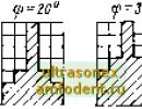
2 8; 3.0 m when the DL changes within the range from O (omnidirectional loudspeakers) to (in steps of 2 dB) and for angle values t) from O
The results of these calculations, obtained for B = 3.0 m and DA = 10 dB (as those of greatest interest), are presented graphically in Fig. 3.2. Here
Rns 3 1 for calculating the stereo effect zone
for each individual case the calculated values of \avg and p are given. The stereo effect zone is shaded, and the zone of the listening seats for which the calculation was performed is left blank. Note that at B = 3.0 m, the greatest increase in the stereo effect zone is observed at DL = 40 dB and \j 70°, which corresponds to an angle to the loudspeakers of 2ph 140°. Zavn-


Fig. 3 2 Influence of the shape and orientation in space of the directivity characteristics of loudspeakers on the size of the stereo effect zone
The symmetry of the coefficient p on the degree of directivity of the AL loudspeakers, obtained for different values of the angles r, is shown in Fig. 3 3.
The data obtained indicate the following: a) the smallest size of the stereo effect zone is obtained when using! directional speakers, but located
Fig. 3 3 Dependence of the coefficient of utilization of the listening area by the tested reproduction system on the degree of directivity of the loudspeakers for different angles of intersection of the acoustic axes of the loudspeakers

so that their acoustic axes are parallel; b) a slightly larger stereo effect zone is provided by omnidirectional loudspeakers! . speakers, c) the greatest expansion of the stereo effect zone is observed when using directional speakers, the acoustic axes of which are directed towards each other at a certain angle.
3.3. Optimal speaker directivity characteristics for stereo playback
The vast majority of currently produced acoustic systems and a significant part of the basic models (see Table 3.1) provide a very narrow stereo effect zone. Firstly, this creates significant inconvenience for the listener, forcing him to position himself on the axis of symmetry of the system. Secondly, the possibility of collective listening in order to obtain a high-quality perceived stereo effect is practically eliminated. For listeners located on the side of the system’s symmetry axis, who perceive only the nearest loudspeaker, the sound essentially becomes monophonic.
This drawback, inherent in most stereophonic sound reproduction systems, is not insurmountable. From Fig. 3.2 and 3.3 it is clear that the use of directional and specifically oriented loudspeakers can be a fairly effective measure for expanding the stereo effect area. In other words, using the directivity characteristics of loudspeakers, it becomes possible to compensate for the effect on the hearing organ of the time difference \Xx,y and the level difference ALx,y by creating at each listening point a compensating level difference of a certain value and sign.
In this case, the compensation equation has the form
;.D.,.+ DH.+ DD(F., = 0 (3-2)
where ДLдф is the compensating level difference, in decibels, created at a given point due to the difference in the directional characteristics of D1(1) and D2(11;2) loudspeakers, and is defined as
D Ld = D, W - D, W = /S. + 20 Ig + /Co
Typically, the values of ДЛд(ф) are calculated only for the central KIZ, since stabilization of its location during the lateral displacement of the listener is a necessary and sufficient condition for stabilizing the entire panorama. This follows from the fact that the slope of the curves characterizing the relative displacement of the KIZ in the AL or Dt function does not depend neither from the size B, nor from the listener’s coordinates at y>B.
From (3.3) it follows that there are many forms of optimal directional characteristics, since the determining factor is their difference. Most often in practice, two ways are used to obtain the difference DLdf
The most common method for two-channel stereophony is the creation of loudspeakers that provide for each listening position the values of the difference in directional factors that ensure directional radiation of sound only in the horizontal plane. In this case, in the vertical plane, sound radiation should be as non-directional as possible.
Obtaining the directional characteristics of each of the loudspeakers in the horizontal plane, which is monotonic as a function of the angle and, moreover, without sharp bends, is possible if precise compensation (complete neutralization of the effect on the hearing organ) of the values of Axx.y and \Lx,y is carried out only for points forming a straight line line parallel to the speaker base.
The results of calculations Add1(φ) for different values and distances уо are presented in Fig. 3.4. For ease of comparison, each curve obtained was normalized and, in addition, they were plotted in decibels. From Fig. 3.4 it follows that the shape of the optimal directivity characteristics of loudspeakers depends on V0 and B; the larger B and the shorter the distance to the co.m-yaeisacin line, the sharper the directional characteristics of Gr1 and Gr2 should be;

O -5 -10 -15 dV -20 -15 -10 -5 O

Fig, 3.4. Optimal directional characteristics for the transmission of spatial information for the right (solid lines) and left (dashed lines) loudspeakers of a stereophonic acoustic system for different bases at yb = 2 m (a) and different Uo prn B = 1.8 m (b)
prn!/o>1.5 m the influence of this factor is significantly reduced; the acoustic fundamentals of loudspeakers with optimal directivity (depending on the selected values of B and y) intersect on the axis of symmetry at an angle of 80-120°; the change in directionality of each loudspeaker within an angle of 60°, counting from its acoustic base for cases of greatest practical interest (B = 2.8-3.0 and Uo>\.5 m), is 6-8 dB. Note that the results of these calculations agree quite well with the data in § 3.2. To reduce the influence of the vertical directivity of such loudspeakers and the results obtained, the loudspeakers should be located at the level of the listener's ears, but if the vertical directivity is insignificant, then the height of the speakers is indifferent. You just have to remember that their extreme rise leads to an unnatural height of the stereo panorama.
Another, less common currently method of expanding the stereo effect zone (equally suitable for stereophony and quadraphonics) is the use of loudspeakers that have a certain form of directional radiation in the vertical plane and no directionality in the horizontal plane. To obtain the desired effect, the speakers should be installed lower (this is the preferred location).
WITH I’ll be honest: what didn’t happen didn’t happen. Never in my life has this product come across my desk. A rare car in our area, yes, sir... I have long been tempted to find out how the stereo effect zone expanded in such an unexpected way is perceived by ear. After all, what have these engineers done (see Figure 5). They added one more channel to the main left and right channels, shifting the phase for each of them by 90°. I suspect that the price for this decision was a deterioration in the localization of sound sources, and simply that the stereo panorama was “smeared out”. However, I have never listened to this device in my life, yes sir...

 In general, this machine looks very interesting. Yes, here’s another thing: no matter how hard I tried, I couldn’t find a Western analogue of this mastodon (but this is really interesting). First of all, I started looking for it among the products of the AKAI company, based on the fact that the Rostovites “removed” the labyrinthine speakers 6ASL-1 from Akaev’s Jet Stream speakers (more on this below). So: among Akaev’s designs of that time there were quadraphonic systems, but no matter how hard I tried, I couldn’t find such an unexpected thing from them. I also went through the catalogs of other heroes of that time, however, with the same result... Although, of course, it is not a fact that it was not stolen from some less eminent manufacturer, or I did not carefully study the catalogs of that time, or I did not come across the right one catalog - yet quite a few of these catalogs have survived to this day... In general, fearing to make a mistake, I put off publishing this post since the spring, but now I finally decided: I screwed up, screwed up, and to hell with it!
Yes, sir... So: as I already wrote above, the Rostovites copied the design of the acoustic systems of this device from the Japanese, from the labyrinthine speakers Jet Stream (jet stream) from AKAI, which were fashionable at that time. They did this without any twinge of conscience, that is, with an accuracy of up to a millimeter. The only thing that the Rostov engineers had to change was to add a 3GD31 tweeter to the speaker, and they also had to install a filter for the tweeter. At that time, we didn’t have a broadband head of the required dimensions and power, and therefore our engineers, without a second word, turned the Japanese system upside down (so that its center of gravity was at the bottom, and the Twitter, as it should be, at the top) and added this most unfortunate Twitter there, yes -s... The decision, as for me, is more than sensible.
Finally, I’ll give you a nostalgic Japanese advertising photo of those years (it exactly shows an AKAI quadraphonic system equipped with Jet Stream acoustic systems).

"ROSTOV-DON-101-STEREO"
V. Kiyashko, N. Sidnevets, Y. Savkin
"Radio" No. 3, 1978
WITH The Rostov-Don-101-stereo surround sound system consists of an amplification-switching device and four two-way 6ASL-1 labyrinth-type loudspeakers. It allows you to listen to monaural programs with a surround sound effect and stereo programs with an extended stereo effect area. The signal sources can be a tape recorder, an electric player or a radio receiver (tuner).
Technical characteristics of the UCU:
Nominal range of amplified frequencies, Hz 40... 18 000
Uneven amplitude-frequency characteristics of channels in the nominal frequency range, dB, no more than 2
output power each channel at 4 Ohm load, W:
nominal 10
maximum 15
Electrical voltage harmonic distortion at rated output power in the rated frequency range, %, no more than 1
Relative interference level, dB, no more, from input:
ceramic pickups (“V. K.” and tape recorder (“Magn.”) - 60
magnetic pickup (“Sv. m.*) – 50
tuner (“Receive”). . . - 50
Sensitivity, mV, from input:
“Sound.” To." and "Magn." . . . 200. . .250
“Sound.” m." 3...5
"Reception." 20...25
Tone control limits at frequencies 63 Hz and 16 kHz, dB, no less. . ±10
Limits of smooth volume control, dB. not less than 60
Volume reduction, dB, not less than -15
Phase mismatch of output voltages between stereo channels in the frequency range 1. ..6 kHz, degree... 90 ±15
Damping coefficient, at least 8
Power consumption, VA 150
Dimensions, mm 530 x 355 x 136
Weight, kg 16.5
Technical characteristics of loudspeaker 6ASL-1:
Rated power, Tue 6
Efficiently reproduced frequency range(with frequency response unevenness 15 dB), Hz 63... 18,000
Nominal input impedance, Ohm 4
Average standard sound pressure, Pa 0.1
Total harmonic distortion by sound pressure at rated power at a frequency of 1 kHz, %, no more than 3
Dimensions, mm 1 70x 285x 430
Weight, kg 7
The block diagram of the Rostov-Don-101-stereo amplification and switching device is shown in Fig. 3. Input signal sources are connected to connectors X1 - X4, speakers - to connectors X6 - X9, stereo phones - to connector X5. The selected signal source is connected to the input of amplifier A1 by pressing the corresponding switch button S1. The amplified signal through switches S1.5 (“Quiet” is a step volume control) and S1.6 (“Stereo”) is supplied to a dual variable resistor R7, which is a volume control. By pressing the S17 (“Loudness”) button, you can connect the loudness circuits C2C4R5 and C3C5R6 to it, which improve the quality of sound reproduction at low volumes. The position of the S1.6 button, shown in the diagram, corresponds to the supply of a monophonic signal to the input of the VCU. The outputs of amplifier A1 and the volume controls in this case are connected in parallel.

The sensitivity and amplitude-frequency response (AFC) of the two-channel input amplifier A1 change depending on the choice of signal source. The necessary switchings are made by an electromagnetic relay (not shown in Fig. 3), located in the amplifier and controlled by the S1.3 button.
When operating from a magnetic pickup (button S1.4 is pressed), relay K2 is activated, connecting the X3 connector to the amplifier input. The relay located in amplifier A1 does not work, since the power supply circuit of its winding is open (button S1.3 in the position shown in the diagram). In this case, the frequency response of the amplifier corresponds to the standard one, and its sensitivity is 3...5 mV.
Pressing the S1.3 button causes relay K2 to release (the amplifier input is connected to connector X4), and the relay located in the amplifier is activated. As a result, the frequency response of the amplifier becomes linear and the sensitivity decreases to 20...25 mV.
The input amplifier has another two-channel path, which is used when operating from a ceramic pickup and tape recorder. They are connected to the amplifier by the contacts of relay K1 (its power circuit is switched by the contacts of the S 1.1 button). The outputs of the amplifiers of this path are connected to the output of amplifier A1 by the contacts of another relay (also not shown in the diagram). In this case, the outputs of the signal amplifiers of the magnetic pickup and radio receiver are turned off.
From the motors of the variable resistor R7, the signals go to the inputs of the emitter followers A2 and from them to the tone controls for high and low frequencies, preamplifiers A4 and A5 and phase shifters U1 and U2.
The output signals of the phase shifters, phase-shifted by 90° relative to each other (in each channel), are fed to transformerless power amplifiers A6.1, A6.2 and A7.1, A7.2. These amplifiers are powered by a bipolar source located in the G1 power supply.
To control the level of output voltage, dial indicators P1 and P2 are used. connected to the outputs of power amplifiers through rectifiers U3 and U4.
All functional units of the UCU, except for the phase shifters, are made according to known schemes and do not have any fundamental features.
The schematic diagram of the phase shifter of one of the channels is shown in Fig. 4.

Its input device is a cascade based on transistor V1 with a shared load. The phase-shifting circuit itself, consisting of resistors and capacitors, creates at the input of the composite emitter followers V2, V4 and V3, V5 two signals with the required (90°) phase shift in the above audio frequency range. These signals are amplified by cascades on transistors V6 and V7 and fed to power amplifiers. The same signal levels at the output of the phase shifter are set with trimming resistors R26 and R27.
To obtain surround sound, the speakers are installed in one row (Fig. 5) at a distance of 100...150 mm from the wall. The distance l between the speakers of the left and right channels is chosen depending on the size of the room.
HIGH FREQUENCY
ACOUSTIC UNIT WITH CIRCULAR DIRECTIVE DIAGRAM
G. STEPANOV
A big disadvantage of modern dynamic loudspeakers is their sharp directivity characteristic in the region of higher sound frequencies, which creates certain inconveniences when listening to monophonic programs and narrows the stereo effect zone when using conventional speaker systems in stereophony.
In various domestic and foreign literature, a figure (Fig. I) has been repeatedly presented, illustrating the influence of the location of loudspeakers on the stereo effect zone. To expand the stereo effect area, many fans of stereophonic sound reproduction use one or two closed-type loudspeakers in each channel, placing them in the corners of the room, as shown in Fig. 2.
High-frequency acoustic units produced by a number of foreign companies are made in the form of a cube, on the inside of each face of which a loudspeaker is located (6 pieces in total).
The use of omnidirectional emitters not only expands the stereo effect area, but also allows you to significantly reduce the required room area from 18-20 to 12-
Rice. 1. Areas of noticeable stereo effect:
a - when placing single loudspeakers in the corners of the room b - when placing a system of three loudspeakers in each channel along the narrow side of the room.
Rice. 2. Place speakers in the corners of the room.
The author of the article proposes the design of a high-frequency acoustic unit with a circular directional characteristic in the horizontal plane, with an operating frequency range from 5-6 to 18-20 kHz.
The design uses domestic loudspeakers 1 GD-3 RRZ with the following main parameters: average standard sound pressure 0.3 p!m2, natural frequency of mechanical resonance 4.5^ ± 1 kHz, total electrical impedance module at a frequency of 630 Hz - 12.5 ohm, rated power 1 etp, operating frequency range 5-18 kHz.
The general view of the unit is shown in Fig. 3. The spherical front of the sound wave from loudspeaker 1 (the figure shows a section of the loudspeaker diffuser) falls on the dispersing lens 2. The sound vibrations reflected from the lens have a circular directional characteristic in the horizontal plane. Calculate the generatrix of the lens
tan in such a way that the directivity characteristic of the loudspeaker is repeated in the vertical plane. To increase the sound pressure and expand the directivity characteristics in the vertical plane, the unit uses two loudspeakers.
When assembling the unit, the loudspeaker with a nylon mesh 6, which protects it from dust, is glued to the plate 4 and the ring 5 pressed into it. Then the entire assembly is attached to the housing 3 using stands 7. Stands 7
Rice. 3. General view of the acoustic unit:
1 - loudspeaker; 2 - acoustic lens; 3 - body; 4 - duralumin plate; 5 - ring; b - nylon mesh; 7 - racks: 8 - base; 9 - couplings.
RADIO No. 4, 1973, O 39
The sound card is the central, but not the only device in a computer audio system. How to amplify the sound, on what and under what conditions to listen to it, so that it is adequate to the capabilities of the sound card and brings pleasure? Buy new or use old?
Speaker systems and amplifiers made in USSR, which, thanks to their serious size, seem to many Russians to be a standard for all time, of course, still have gunpowder in their flasks. But keep in mind that in devices ten to twenty years ago, many things could have become unusable. The electrolytic capacitors have become thin, the potentiometers are greasy, the diffusers are frayed, the housings are dry, etc. Of course, if the speakers are well preserved, the sound will be good, but progress does not stand still, and even with relatively inexpensive modern acoustics you will get better dynamics and a more refined stereo image . The market is flooded with elegant active speakers with great sound. For just fifty dollars you get everything in one: a passable stereo amplifier and decent speakers.
Computer audiophiles are mostly faced with the problem of choosing computer acoustics. And pairing such systems with a computing friend within the framework of an average Russian apartment (12 square meters per person) is significantly different from purchasing, for example, a home theater for installation in a separate spacious room of a country mansion.
Stereophony and stereotypes
Properly implemented stereophony allows you to place voices-sounds in space, clearly separating them from each other, which not only improves and facilitates perception, but also recreates the emotional atmosphere - so to speak, letting the genie out of the bottle. It is for the genie of sound that audiophiles pay a lot of money. It is generally accepted that a stereo effect is when sound runs from left to right and vice versa, or when some instruments come from the left speaker, others from the right. In fact, people who think so have either never heard real stereo sound, or they are not given the ability to hear by nature.
Regardless of the physiological characteristics of the listener, the quality of the stereo effect is influenced by three interrelated parameters:
removal of the listener from the line on which a pair of speaker systems (stereo base) is located;
stereo width (distance between channel emitters);
directionality of acoustic systems.
By choosing a stereo base width of less than 2 m, on most speaker systems at a distance of about a meter - a typical diagram for a computer jack - we obtain the width of the zone of optimal stereo effect (in diagrams 1 and 2, the zone boundary is indicated in red) of about 20 cm.
van_SG_stereo_classic.gif
With a narrow stereo base, our ears find themselves (due to the fixed distance between the eardrums) outside the stereo effect zone if the distance from the line connecting the channel emitters is not enough. A little head to the left or right - and only one ear is in the zone of maximum stereo effect. If you narrow the stereo base, you won’t be able to see the true stereo picture like your ears: you’ll have to move the speaker systems deeper, beyond the plane of the monitor screen. Unfortunately, you can vary only within the depth of the monitor, since it is usually located on the table close to the wall. Otherwise, you will have to move at least a meter and a half away from the “monitor-speakers” line, which is acceptable only for those who suffer from farsightedness and have remote keyboards. As an experiment, the speakers can be hung from the ceiling, pointing down, and using the distance to the ceiling to achieve the required distance (if the cables are long enough and it is generally possible to lay them more or less aesthetically).
Contrary to popular belief about the responsibility for the stereo effect of high frequencies, which determines the range - from 300-600 Hz to 3000-5000 Hz. The stereo effect is generated not only by the difference in sound pressure, but also by more subtle matters of sound. Avant-garde advanced stereo effects are based on phasing (rolling 180 degrees, that is, in antiphase) of sound components from the above-mentioned frequency range. Theoretically, waves in antiphase, mutually adding, should absorb each other, but in practice, due to the fact that we have two ears located not at zero distance from each other, annihilation does not occur. The speakers emit sound waves in antiphase, creating a complex sound field with redistributed energy, which also contributes to reflection from the walls of waves that are out of phase. Paradoxically, in this case we clearly hear imaginary (!) sound sources. The sensations are amazing - sometimes it seems that the sound is coming from behind you, although there are no speakers there at all (see, for example, our articles on the Sony MDR-DS5100 headphones - and the Creative PlayWorks PS2000 Digital speaker system - /multimedia/9049). True, it is only possible to guess at which point in the space of the room the effect will be most pronounced. The wavelength in the stereo frequency range is approximately 1 m to 6 cm. Move your hearing aid, say, half a meter forward and it is very likely that the effects will fade into obscurity. Therefore, it is better to place the speakers in such a way as to reserve the maximum area of space in advance, subsequently determining the zone of the best stereo effect experimentally. Of course, this is much easier to do with a wide stereo base.
Note that previously stereo effects were based on the difference in volume between channels or on pushing the voices of instruments left and right, as in the recordings of The Beatles from 1960. As sound recording and knowledge of psychoacoustics improved, phase delays between sounds on different channels began to be used. So, if a sound of equal amplitude is released from the left channel with a delay of more than 3 ms relative to the right, the sound will begin to predominate in the right channel. Accordingly, if there is a delay in the right channel, from the point of view of the human hearing system, the sound will escape to the left channel. If the delay exceeds 60 ms, instead of a virtual stereo effect, we will hear discord (similar to an echo) of sounds coming from the left and right channels.
If the stereo base is too wide (more than 4-5 m) and the use of compact speaker systems, a lot of surprises pop up, mostly negative, but with our everyday footage, such a scope is not very interesting. By the way, for professional listening the base length is selected from 3 to 5 m, and for home equipment up to 3 m. The rotation angle of the speakers relative to the base line ranges from 45 to 75 degrees.
Often we do not have the opportunity to place speaker systems according to classical rules, in strict symmetry, etc. Do not despair - there are many completely acceptable options. One of them for a small room is presented in Diagram 2. The price to pay will be narrowness (with a base of up to 4 m at a distance of about 2 m - less than half a meter) and asymmetry of the optimal listening area, and a plus is good localization of sound sources due to the expansion of the stereo base and weakening of the acoustic pressure at low frequency resonances.
When placing speakers, do not forget the common truths: do not place them in corners along a wide wall; do not lift it up to the ceiling, putting it, for example, on a cabinet and not tilting it towards the listener’s head; do not arrange a listening area in nooks formed by massive furniture and various construction appendixes. For the rest, you can safely experiment. For example, if you think there is not enough bass, try to arrange your listening position so that your head and ears are as close as possible to the wall opposite from the plane of the speakers.
Removal of the optimal listening point and the distance between speaker systems are interconnected through the directivity of the latter. It's no secret that at different angles to the speaker axis you will get different amplitude-frequency characteristics. The directionality is especially pronounced at high and medium frequencies. Experts unanimously welcome wide-directional speakers, in which the roll-off of the highs and the turbulence of the mids are minimal as the deflection angle increases. No one doubts that if the sound does not deteriorate at an angle, then no matter where the listener stands (in a half-plane), the speaker will sound the same everywhere. Note, one column. But with two - the war in Crimea, everything is in smoke. It seems that they have not yet learned how to properly evaluate and measure the quality of recreating a stereo image with a pair (!) of speakers. The statement that wide-directional speakers provide better localization of sound sources in the stereo effect zone is quite controversial. Acoustic engineers insist: the wider the directivity, the smaller the area of the stereo effect zone. There is no consensus on the location (longitudinal) of the ideal stereo effect point. Some argue that this is one and a half lengths of the stereo base, others insist that this is exactly one length (naturally, this implies equidistance from the speaker systems).
Multichannel systems
With the invasion of multi-channel sound into our lives, when we have to shove at least five satellites plus a subwoofer around the room, the task of determining the optimal listening area becomes incredibly complicated. It is possible that the optimal listening point will not be in the area of a cozy chair, but somewhere in the area of the chandelier.
Audio/video sellers unanimously trumpet that without five satellites you will not hear surround sound. Note that the center channel is only needed to increase the number of seats in your theater. Imagine a whispered phrase coming from the left channel. Then the viewer, acoustically shielded by household members and guests sitting on the left, simply will not hear her. So that people on the edge would not be lost in guessing what the hero on the left said and what the heroine on the right answered, a special channel was allocated into which sound engineers try to combine all the dialogues. If the entire stall consists of two chairs, the central channel is not so necessary. For listening on a personal computer, it is not relevant at all. The localization of sounds in the center is perfectly recreated by the left and right fronts through the good old stereo effect. For example, the extremely successful five-component (4.1) system Altec Lansing ADA-890 was the first among computer speakers to receive a THX certificate, but there is no trace of a central channel (see). A subwoofer is more appropriate - without it, dynamics hidden in multi-channel digital formats loses its meaning .
A separate issue is the placement of rear (surround) acoustics. Dolby Labs recommends that the rear be spaced wider than the front (see diagram 3), with the angle between the rear speakers at the point of ideal effect being 140 degrees, and all speakers being equidistant from it. That is, non-subwoofer speakers should be placed in a circle.
I dare say that we have a hard time with round rooms, so we’ll have to get smart with the rear acoustics. Please note that according to Dolby recommendations, the distance between the front speakers is equal to the radius of the speaker circle. Then, if the marked distance does not exceed a meter (typical for the classic arrangement of computer speaker systems next to the monitor), then the speakers of the surrounding channels should be located at a distance of only one meter from the listener. And this is extremely problematic to implement in practice. All sorts of tripod stands will constantly get knocked over and dropped along with the speakers. Ideally, it would be good to place the speakers on a special shelf or hang them on the wall, but the wall or shelf will probably be further away than necessary.
The ratio of distances recommended by the above diagram is not universal and works within certain limits. Let's say, it is unlikely to be valid for ten meters and even less so for ten centimeters. It is not difficult to foresee that at short distances (less than half a meter) the size of the speaker systems will have an impact.
If you believe the same Dolby (which knows the secrets of spatial sound firsthand), an acceptable listening area should be sought inside a circle, the radius of which is approximately equal to half the distance between the front speakers. Obviously, the shorter this distance, the smaller the area of the optimal listening area. It should be noted that placing your ears in the so-called acceptable zone does not guarantee one hundred percent spatial sound. Some of the volumetric effects will remain, but some will be lost. The optimal zone may turn out to be much less than acceptable; this depends on a number of nuances.
A surprise awaits those who do not like to move away from the monitor, especially when listening to music or watching movies with multi-channel sound. Typically, the user sits at a distance of 50-70 cm from the display and front speakers. And this, with a distance between the front speakers of about a meter or more (as a rule, music lovers arrange them this way), leads to a discrepancy between the position of the ears and the ideal listening area due to the fact that the latter runs almost half a meter behind the listener’s head. Bringing the front speakers closer to 50-70 cm (on the sides of a 15- or 17-inch monitor) brings the ideal listening point closer to the user’s ears, but leads to extremely undesirable consequences. Firstly, to obtain true surround sound, the rear speakers will have to be placed even closer (the new radius is the notorious 50-70 cm!). Secondly, the area of the optimal listening zone becomes even smaller, shrinking almost to the size of the skull. Third, the area of acceptable listening is shrinking to the point where there is simply no place for another listener in the space of true surround sound.
However, a reasonable thought arises: why bother with the placement of speakers if no one bothers you to adjust the volume of the center, front and surrounding channels in the same audio card mixer, thereby compensating for the difference in removing the speakers that are not scattered according to the rules. However, there is a catch here. The fact is that even identical speaker systems have different frequency characteristics at different volumes! That is, heavily loaded and lightly loaded speakers can sound different. It seems that it is much easier to sing quietly than to sing the same thing loudly without cackling or without losing your voice. Adjusting the volume of individual channels can be the death of surround sound, or you can get away with it. Here's how lucky you are with a specific speaker model, and how your personal preferences for sound volume will affect you.
It should be emphasized that the use of different caliber speakers (in particular, in terms of power) for the rear and front, as well as for the center, is not an easy way from the point of view of recreating spatial sound. Of course, you can hit the bull’s eye the first time, but the chances, alas, are not great.
To properly set up surround sound without the hassle of arranging (or selecting) speakers, they resort to more subtle means than turning up the volume. In drivers of advanced sound cards (and very rarely in amplifiers-decoders of multi-channel speaker systems, see, for example, 12561) you can play with the delay between the front and rear. For example, Creative SB Audigy2 introduced an automated procedure for calibrating multi-channel speaker systems, which has a non-trivial algorithm.
For the correct placement of speaker systems in the most general terms, two approaches can be recommended. The first (compromise) is the traditional arrangement of the front satellites in the plane of the display screen, and the center - on top of the monitor. Then, with a small distance between the front speakers and God knows how the rear is attached, at the very least, we will still get multi-channel sound right at the workplace, but you will have to listen alone and without moving, so as not to jump out of the narrowed surround sound zone. With a fairly wide placement of the front speakers and, as a result, no headaches about where to place the rear speakers, we will get a decent zone of optimal sound, but it will be outside the typical workplace. That is, when listening to multi-channel sound, you will have to move the chair back.
The second (far-sighted) approach consists of experimentally placing speakers away from the monitor in order to expand the optimal listening zone, as well as making spatial sound more realistic and more clearly localized.
The placement of the center channel speaker on the front of the monitor (offered by many multimedia manufacturers) cannot be considered a good solution, even with a wide arrangement of front speakers. Yes, in a full-scale home theater it is customary to pile the central speaker on top of the TV, but at the same time the front speakers are moved apart by more than two meters, and the spectators-listeners sit at a respectable distance. If, nevertheless, the center channel speaker is placed on the monitor, and the front speakers are placed at random, the sound connoisseur will have to move much further away compared to the usual working distance. Practice shows that sometimes it is better to abandon the central channel altogether. Unfortunately, the result depends on the specifics of the speaker systems. Therefore, the best solution is to remove the front and center speakers from the listener’s place of permanent residence, placing the center on a stand (or suspension, or on a shelf) behind the monitor, and the front along the edges of the table or on the shelves adjacent to it (see diagram 4).
van_SG_true5_1!!.gif
It’s easy to say, arrange the speakers this way and that way, when in the room there’s a closet bulging out, and there’s some kind of immovable crap sticking out there. And is this spatial sound really that good if you can get by with good stereo? There is no arguing about tastes, of course. Do you want new, truly thrilling sensations? Then go ahead!
A computer desk freed from speakers and placed perpendicular to a long wall is one of the controversial solutions to optimize the placement of acoustics (diagram 5). The front and center speakers need to be placed on something so that they are higher than the table and monitor, otherwise shielding and diffraction cannot be avoided. It’s also bad that the optimal listening area has disappeared so that most of it covers a space inaccessible to listeners.
In the case of a corner table pressed against two walls, we get a rather bad option (diagram 6). One of the rear columns turns out not to be sewn onto the mare's tail. Even if you hang it from the ceiling, the asymmetry of the walls will still do its dirty work, and everyone will bang their heads on the rear hermit speaker, hanging, of course, in the aisle. With stereo sound, yes, everything is fine: rear speakers on the walls can serve as a good stereo expander in double stereo mode. To still qualify for surround sound, you will have to bring the rear speakers closer (diagram 7).
van_SG_true5_1!!.gif
Everything said above about speaker placement applies to acoustics with five or more satellites, but in the case of a home theater it can easily be projected onto four. With games it’s more difficult - you’ll have to look for the treasured sweet spot experimentally or limit yourself to headphones.
| Features of modern speaker systems A few words about the designs of computer speaker systems. When the acoustic design of the speakers is closed, the response at low frequencies leaves much to be desired, as the elasticity of the air trapped inside the speaker system box affects it. Here, by recoil we mean the acoustic pressure developed in the sounded space. Air elasticity increases the fundamental resonant frequency of the bass speaker head, the more the larger the diameter of the diffuser and the smaller the volume of the box. A large diffuser emits low frequencies much more efficiently, but in the age of widespread miniaturization, this makes few people happy. To make a speaker louder, they go three ways: increase the volume of the case (not fashionable and not cheap); they make the low-frequency diffuser heavier (the disadvantages are obvious: try swinging and braking when necessary) or increase the flexibility of the diffuser suspension; They deceive nature by inverting the phase of the wave emitted by the rear part of the diffuser - they insert a port (usually a pipe) of a bass reflex. As far as we know, the calculation of a bass reflex does not have a unique analytical solution, that is, when determining the size of the ill-fated pipe, they use the trial and error method, using semi-empirical dependencies. If the pipe, according to estimates, comes out too long and does not fit into the speaker body, then the bass reflex is bent, or less often, almost at random, the neck of the pipe is profiled. As a rule, it is placed on the front panel of the speaker, but they do not disdain the back panel, although there are also more logical solutions such as a port deployed along the perimeter at the bottom of the speakers. The anus option is perhaps the most inadequate. Of course, the phase inverter best turns over the wave that coincides in frequency with its own resonant one. The remaining frequencies will be spat out insofar as. Ideally, low-frequency waves should be flipped 180 degrees to be in phase with those emitted by the front surface of the diffuser. Not all dynamic heads are good for bass reflex speakers. Any speaker has its own resonance and there is such a thing as the quality factor of the oscillating system. With a low quality factor, the speaker will try to ignore external influences at its own resonance frequency. With a high quality factor, on the contrary, sway it to the beat until you become stupefied. Do you remember the bearded example from physics about soldiers walking out of step across a bridge? Well, during normal operation, it is unlikely that you will be able to apply a voltage of an insidious frequency to the speaker so that it falls apart - rather, the coil (which is attached to the diffuser and oscillates in the gap of the magnet) will bark. The more mobile the diffuser suspension, the higher the quality factor, as a rule. Experience shows that exceeding a certain limit in terms of quality factor is fraught with danger. In particular, there is a risk of getting excessive convexity in the frequency response of the acoustic system and unpleasant to the ear (albeit powerful) low frequencies. As always in technology, we come across the need to find a compromise. Either your head will get stuck or your feet will drown. The speakers will receive either high sensitivity (easily driven by any amplifier) and will hum, mumble and hoot around the bass reflex frequency, or low sensitivity (which, with proper design of active acoustics, can be easily avoided by matching the built-in amplifier with the speakers), but without bass reflex hum. The bass reflex, a constructed clunker, coupled with an unsuccessfully selected speaker, smears percussive sounds over time and introduces low-frequency after-sounds into purely harmonic tones. Thus, the bass reflex helps with the now fashionable miniaturization of speakers with classic speakers, but it is fraught with many difficult to predict surprises, most often unpleasant. |
About room acoustics
I hope there is no need to prove that the same acoustic system can sound differently in different rooms. Reverberation time is directly proportional to the volume of the space being sounded and inversely proportional to something called the total absorption of the room. The longer the reverberation time, the more intricate and powerful the echo. The so-called total absorption of a room is most often determined empirically. The absorption of some objects (chairs, armchairs, people) is known, but depends on the frequency of sound. For example, at a frequency of 100 Hz it is three times less than at a frequency of 4000 Hz.
In living rooms with a volume of up to fifty cubic meters, the reverberation time is short and is about 0.3 s. In these types of rooms, listeners mainly perceive sounds reproduced directly by loudspeakers. Sounds reflected from walls have too little delay for our hearing system to respond to them. For comparison, the reverberation time of large concert halls reaches five seconds.
Any room causes a selective redistribution of the power of certain frequency components. This is most noticeable in pure tones. The effect is caused by the formation of standing waves (the wave front does not move in space, the attenuation is small) at the resonant frequencies of the room. The main resonant frequencies are determined by the distance between opposite walls, between the ceiling and floor, as well as their geometry. In addition to the main ones, there are many additional resonances that extend into the region of higher frequencies. So, in the frequency range up to 100 Hz for a large living room you can detect about forty (!) resonances. In small rooms, even low-frequency beats are not excluded - a very unpleasant phenomenon to the ear. It’s not for nothing that Hi-Fi acoustics experts note the unpleasant strangeness of the bass sound of powerful floor-standing speakers in small rooms. But in rooms with high ceilings (more than 3 m), the bass of modest bookshelf speakers can sound wonderful. It’s not easy to drown out any room in the low-frequency range. Here you can’t get away with thick, heavy carpets and dense gathered curtains, although without them the picture is often completely gloomy.
For mid and high frequencies with a stereo pair of speakers, according to audiophiles, a good result is obtained by fencing the rear of the optimal listening area with sound-diffusing objects. However, for multi-channel acoustics you will have to look for other ways. The same carpet (fluffier and warmer) on the floor, pimply soft thickened wallpaper, foam ceiling tiles and curtains on the windows will give noticeable positive changes. For most typical living spaces this is sufficient. The presence of upholstered furniture is implied by default, because you can’t sit cross-legged to listen to music.
You will have to get rid of yourself in rooms of extraordinary shape, in which would-be architects create acoustic pockets of various kinds, including low-frequency resonators. The owners sometimes also make mistakes with the placement of acoustics, and then are surprised that the tone drops. Alas, it is impossible to give a universal recipe here; there are too many unpredictable combinations.
Ideally, you need to take care of sound insulation, that is, not only to dampen the listening room, getting rid of reflected sounds, but also to minimize the passage of sound into neighboring rooms. For this purpose, sound-absorbing, rather than sound-reflecting or vibration-damping materials are used. Sound-reflecting materials will prevent sound from penetrating into neighboring rooms, but it is not difficult to guess what will happen in the room with the sound source. It is much easier to reflect sound than to absorb it. For maximum effect, the thickness of the absorbing layer should be comparable to the wavelength, and at low frequencies this is from several meters to one and a half dozen.
Modern noise-absorbing materials (open-cell foam based on polyurethane, etc.), widely used in car audio tuning, are effective starting from 200 Hz, with maximum absorption at certain frequencies, for example 1 kHz. Resonant type sound absorbers (perforated mats) are good only at certain frequencies. The most effective, over the entire frequency range, are pointed wedges made of sound-absorbing materials, but the dimensions of such wedges must be so large for low frequencies, which leads to wild costs and an equally wild appearance of the room. I remember that to soundproof residential premises, avid music lovers covered the walls with cellular packaging pallets intended for transporting chicken eggs, in addition filling the wall space with mineral wool. This creation has the same look, but you could enjoy full sound at any time of the day. So serious sound insulation is a troublesome, expensive and thankless task. The neighbors will not appreciate your impulse, but your household will be on the warpath.
However, everything is good in moderation, and you shouldn’t get carried away with dampening the room. The exception is the case when it is necessary to carry out correct measurements, for example, to measure the frequency response of acoustic systems, etc. Otherwise, re-muffling is hardly justified, since it will lead to an unnatural and unexpectedly quiet sound, however, with a very clear stereo image with detailed localization of sound sources. Here's a compromise: either spatial effects or natural sound.
B. Urbansky. Electroacoustics in questions and answers. - M.: Radio and communication, 1981.
V. K. Iofe, M. V. Lizunkov. Household acoustic systems. - M.: Radio and communication, 1984. - 96 p.
M. Ephrussi. Reducing the resonant frequency of heads, Radio, 3, 1975.
(http://www.noisebuster.ru/material/aa.shtml).
Stereophonic sound reproduction has now received universal recognition for its higher (compared to monophonic) natural sound.
The carriers of stereophonic information are the temporal DT and intensity AL differences between the signals of the left and right channels.
Rice. 1. Distortion of the spatial panorama when the listener moves laterally
The intensity difference is determined by the expression DL=201g(P 2 /P 1), where P 1 And P 2 - sound pressures developed by the left and right loudspeakers, indicated IN 1 And AT 2 in Fig. 1.
If the listener is positioned asymmetrically relative to the acoustic systems of the left and right channels or if the characteristics of the nodes of the stereophonic complex are not identical, additional time and intensity differences in the signals arise. This leads to the fact that the actual stereo panorama will differ from the original one (conceived by the sound engineer), i.e., spatial distortions arise.
The appearance of spatial distortions is also accompanied by a number of other changes. First of all, the separateness of perception of individual parts of the sound panorama is lost, and the musical balance in the stereo panorama or volume balance is also disrupted.
Recent studies have shown that with an additional difference DL=3 dB, the sound source shifts by 0.4 m towards the loudspeaker emitting a signal with a higher level, and with DL=6 dB - by 0.8 m. For example, with the introduction of an additional time shift Dt = 0.5 ms with a base of 5 = 1.8 m, the sound from the piano is shifted by 0.5 m towards the loudspeaker emitting a leading signal. These deviations are equivalent to the listener moving along the base line and lead to distortion of the spatial sound panorama (Fig. 1). Sound sources 2 and 4, located in the middle part of the panorama, undergo the greatest displacement from their original position.
For sources located at loudspeaker positions, there is virtually no spatial distortion, since DL>20 dB and DT>3 ms.
With the introduction of an additional time shift Dt = 5...15 ms, localization of the sound source becomes more difficult, the sound becomes booming and three-dimensional. For high-quality localization of a sound source, the value of Dt should be less than 3...4 ms.
To avoid spatial distortion of the stereo panorama, characteristics of low-frequency amplifiers, speaker systems and electric players. devices must meet certain requirements.
Research in this area has made it possible to formulate a number of requirements for low-frequency stereo transistor amplifiers and speaker systems and to justify the corresponding technical solutions.
To obtain low harmonic and intermodulation distortion, transistor power amplifiers must have:
extended frequency range, for which it is recommended to connect the output stages using a circuit with a common collector and compensation for lead and lag;
low overall negative feedback to ensure stability of the amplifier with an extended frequency range and reduce dynamic distortion;
cascades with local negative feedback and the use of complementary pairs of transistors; operating in class A mode;
cascades with galvanic couplings to obtain a linear phase-frequency response;
higher overload capacity to reduce dynamic distortion.
To reduce time shifts, stereo amplifiers must have identical phase-frequency characteristics (1PFC), which is achieved by selecting radio elements with a spread of no more than ±2%.
The coefficient of harmonic distortion in audio amplifiers should not exceed 0.05% in the frequency range 30...20,000 Hz.
Acoustic systems should have, as far as possible, a uniform amplitude-frequency response (AFC) and a phase-frequency response that is close to linear in the range of reproduced frequencies.
Speaker systems for stereophonic sound reproduction usually have a very narrow stereo effect zone. For listeners located to the side of the system's symmetry axis, the sound becomes monophonic. This disadvantage can be mitigated by expanding the stereo effect zone. In other words, by changing the directivity characteristics of the loudspeakers, it becomes possible to compensate for the effect on the hearing organ of the resulting time difference and level difference with an asymmetrical arrangement relative to the left and right loudspeakers.
The radiation directivity characteristics of a mid-frequency loudspeaker at frequencies of 3000...5000 Hz can be. improved if the speaker cone diameter does not exceed 80 mm. Further improvement is provided by the installation of acoustic lenses.
Another disadvantage of the acoustic system is that the loudspeakers have large distortions and uneven frequency response in terms of sound pressure, especially in the lower frequencies of the audio range, where the moving magnetic system oscillates with a large amplitude. The causes of distortion are usually the exit of the voice coil beyond the magnetic gap and the nonlinearity of the elastic suspension of the diffuser.
Greater frequency response uniformity, a reduction in the amplitude of movement of the moving system and, accordingly, a reduction in nonlinear and intermodulation distortions can be achieved by changing the quality factor of the moving loudspeaker system, i.e., the degree of its damping. Damping can be controlled by changing the output resistance of the audio amplifier using positive feedback on the load current or a speed (acceleration) sensor installed on the diffuser. The amount of damping will be higher if the speaker has a higher sound pressure and a lighter cone.
If the frequency response of the loudspeaker is very uneven (±15 dB) in terms of sound pressure, additional intensity differences in the sound of signals are introduced in the audio frequency range across channels. This difference can be reduced with an equalizer, but to do this you need to determine the actual frequency response of both speakers, which is very difficult. In addition, when reducing the unevenness of the frequency response in sound pressure, the equalizer introduces additional time shifts of signals along the channels of the stereo amplifier.
A certain alignment of the loudspeaker's phase response can be achieved by placing the acoustic centers of the dynamic heads in the same plane. However, this measure is often insufficient, since phase shifts depend on the speed of propagation of sound waves along the surface of the diffuser. The best results are obtained by moving the woofer forward in relation to the midrange speaker, and the midrange speaker forward in relation to the tweeter.
An electric player is the third important component of the sound-reproducing complex.
Distortion in an electric turntable is introduced by the pickup head, tonearm and mechanical assembly. The pickup head should have an ellipse stylus, since the shape of an ellipse is more similar to the shape of a record cutter than a sphere.
Significantly less distortion during sound reproduction of a mechanical recording is introduced by multi-radius games (for example, the so-called S-needle), which also improve the reliability of the tonearm following the groove of the record and increase the transient attenuation between stereo channels at high frequencies. Higher sound quality is ensured by a magnetodynamic pickup head, since it has less intermodulation distortion than an electromagnetic head.
To reduce distortion caused by the tonearm, it is necessary to suppress resonances, since at the resonant frequency the mechanical resistance of the cartridge increases sharply.
Resonance suppression is carried out by mechanical damping of the tonearm, damping in the region of lower frequencies is carried out by a flexible connection between the tonearm tube and the counterweight via a rubber coupling.
High-frequency resonance is damped by filling the tonearm tube with wood pulp or carbon fibers approximately 1-10~~? mm, impregnated with epoxy resin without a hardener (the attenuation decrement of impregnated carbon filaments is more than three). The detonation coefficient of the moving mechanism of an electric player (disc) should not exceed 0.1%, and the level of interference from vibrations of the driving mechanism - 60 dB, measured by the weighted characteristic, or - 40 dB - by the wide characteristic.