What are the characteristics of complex geometric AutoCAD objects? Introduction to AutoCAD
As already discussed in Sect. 2.5, if the Command line prompt is Command: (Command:), then you can mark visible objects on the screen and handles will appear on them - small blue squares at characteristic points of the objects. Handles are a very convenient tool for quickly changing a selected object. All currently selected objects form a set.
Let's see what handles are highlighted for different primitives and how you can use them to edit them. The names of the primitives will be given as those issued by the LIST command.
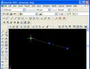
For the LINE primitive, the characteristic points are the end points and the midpoints. Left-click on the previously constructed segment. The segment was highlighted (received a dotted image), and handles appeared at the end and middle points (Fig. 3.1), which indicate that the object was selected for some operation (editing or obtaining help information).
Rice. 3.1. Cut handles
Typically, the handles of selected primitives are blue. However, if you move the cursor crosshair, for example, to the left handle, then the color of this handle will change to green. This means that the coordinate counter in the status bar shows the coordinates of the object's characteristic point. In Fig. 3.1 it can be seen that the left end point of the segment has coordinates X = 90.4567, Y = 119.9414, Z = 0.
Select the first handle of the segment by placing the cursor crosshair on it, then press and release the left mouse button. The selected pen should change from blue to red. AutoCAD displays the following message:
** STRETCH ** Specify stretch point or :(** STRETCH ** Stretch point or [Base point/Copy/Undo/Exit]:)
Enter 90.240 on the keyboard and press the key

Rice. 3.2. Editing a segment using the end handle (specifying a new point by entering coordinates)
The coordinates of a new point can be specified not only by entering them from the keyboard, but also by any of the methods we discussed in section. 2.3. The AutoCAD system will perform an action similar to the STRETCH command, which is described in section. 3.2. In Fig. Figure 3.3 shows an editing process similar to the process shown in Fig. 3.2, but the result is obtained using the mouse. The old position of the segment is shown by a dotted line, the new position is shown by a solid line. With the left mouse button, you must first click on the handle of the end point to be changed and release the pressed left button. Then move the cursor and click again and release the left button only when the segment reaches the desired position.
The remaining options for the pen editing operation are similar to the options for the COPY command, which are discussed in Section. 3.2.
If, after selecting a knob, instead of selecting its new location, you press

Rice. 3.3. Editing a segment using the end handle (specifying a new point with the mouse)
If you select the middle handle rather than the end handle with the mouse, AutoCAD displays text with the same options as in the previous case. Use the mouse to indicate the new position of the midpoint (Fig. 3.4). The segment will move to a new location (the movement is performed beyond the midpoint).
Handles are used in a similar way for other primitives - to indicate a new position of a selected point of an object or to move the entire object to a new location.
For the XLINE (straight) primitive, the base point and two points on the line are highlighted at a short distance from the base point. If you move the base (middle) point, the entire line moves, and if you move the points of other handles, then the base point remains in place, but the slope of the line changes (Fig. 3.5).

Rice. 3.4. Editing a Segment Using the Middle Knob

Rice. 3.5. Editing the slope of a line using a handle
Using handles to edit rays is similar (primitive name is RAY). The beam has two handles: at the base point and at the point that determines the direction. When you move the base point, the entire beam moves; when you move the second (guide) point, the tilt of the beam changes.
On the circle (primitive name - CIRCLE) five handles are displayed: in the center and quadrants (i.e., the extreme top, bottom, left and right points). When you try to move the central handle, the circle moves to a new location, and if you edit the circle using any of the other handles, the circle stretches or contracts, changing the radius (Fig. 3.6).

Rice. 3.6. Editing the Radius of a Circle Using a Pen
The ARC (arc) primitive has three handles displayed: at the ends and in the middle. Moving any of the handles leads to a change in the arc, with the construction of a new arc along three points, one of which was new (Fig. 3.7).
A polyline can be presented in the information window of the LIST command with two names: LWPOLYLINE, i.e. compact polyline, and POLYLINE, i.e. detailed polyline (see section 3.3). A compact polyline is sometimes called lightweight (from the English term lightweight polyline). Handles are highlighted on the polyline at the ends of segments and midpoints of arc segments. When you move the selected handle to a new location, straight segments change in the same way as segments change when they are moved beyond the end points, and arc segments change in the same way as arcs change (Fig. 3.8).

Rice. 3.7. Editing an arc using a pen
The MLINE primitive (multiline) is edited using handles in the same way as polylines.
The TEXT (text) and MTEXT (multitext) primitives have handles at those points that characterize the position or alignment of the text. Any of the handles can be used as a tool to move text to a new location (Fig. 3.9). With some alignment methods (Fit, Aligned), moving one handle can also change the inclination of the text.
The Dimension drop-down menu commands create the DIMENSION, LEADER, and TOLERANCE primitives. Changes to primitives can be performed using any handle, which leads to their movement or change in shape.

Rice. 3.8. Editing a polyline using a pen

Rice. 3.9. Editing text with a pen
However, when editing a dimension using handles, it is recommended to highlight the handles not only on the dimension primitive, but also on the object for which the dimension was set. If you move with the mouse the handle to which the dimension extension line was attached, then not only the main object changes, but also its dimension primitive (Fig. 3.10). As was said in Sect. 2.14, dimensions are usually associative, so changing the main primitive will cause a change in the associated associative dimension. For changes in associativity, see Section 3.6.

Rice. 3.10. Simultaneously edit an object and its associated dimension using a pen
The DIMENSION primitive has handles not only at the base points, but also at the ends of extension lines and at the dimension text. These handles allow you to change the position of the leader line and dimension text (while maintaining the overall design of the dimension as a single whole).
Editing a HATCH primitive (hatch or fill) using handles is ineffective, since the hatch has only one handle in the center of gravity and using this handle the hatch can be moved to a new location (which, however, as a rule, does not make sense). At the same time, we should recall the associative property of hatching mentioned in Section. 2.15. Thanks to this property, editing a path will change the hatch that is attached to it.
The handles of the ellipse and elliptical arc (both are ELLIPSE primitives) are highlighted in different places. For a complete ellipse, their position is similar to the position of the circle handles. When you move the central handle, the entire selected ellipse will be shuffled. But if you move the central handle of an elliptical arc, this will lead to a change in the arc (Fig. 3.11), since the AutoCAD system tries to keep the end points of the arc in the old place.
Rice. 3.11. Editing an ellipse and elliptical arc using a pen
The process of editing a SPLINE primitive using handles is similar to the process of editing a polyline, but moving one handle affects the shape of adjacent sections of the spline (Fig. 3.12).
If you use the handles to edit the TRACE primitive (stripe), then it actually turns into a figure (Fig. 3.13). The SOLID primitive (shape) is edited in the same way.

Rice. 3.12. Editing a spline using a pen

Rice. 3.13. Editing a strip using a pen
Editing POINT primitives (point or anchor point) using handles is obvious.
A convenient tool when editing with pens is the context menu. If you have already selected the handle for editing (that is, it has changed its color to red on the screen) and the right mouse button is pressed, then the context menu shown in Fig. 3.14.
Rice. 3.14. Context menu when a handle is selected
The following actions are possible in this menu:
- Enter - simulate a key press
(cyclic selection of general editing commands); - Move - moving objects (MOVE command);
- Mirror (Mirror) - symmetry of objects (command MIRROR (MIRROR));
- Rotate - rotation of objects (ROTATE command);
- Scale - scaling objects relative to the base point (SCALE command);
- Stretch - stretching objects (STRETCH command);
- Base Point - specifying a different base point to execute the STRETCH command;
- Copy (Copy) - copying objects (command COPY (COPY));
- Reference - select the Reference option for the ROTATE command or the Reference option for the SCALE command;
- Undo (Undo) - canceling the action of the last command (command U (O));
- Properties - manages object properties (PROPERTIES (OKHOCB) command);
- Exit - exits editing mode using the knobs.
Explanations for this menu. General editing commands, as already mentioned, are discussed in Section. 3.2. Managing the properties of objects is discussed in Chapter. 4.
If you have not yet selected a specific handle for editing (not a single handle has changed its color to red) and at this moment you press the right mouse button, then a slightly different context menu is called up, shown in Fig. 3.15.

Rice. 3.15. Context menu when no handles are selected
The structure of this menu is similar to the structure of the previous context menu (see Fig. 3.14) in that it has a group of items related to editing (Move, Scale, etc.), but it now has an item Erase, which deletes selected objects.
The item to repeat the last command is always inserted first into the context menu. If you select a polyline, then a second item additionally appears in this menu - Polyline Edit. Its appearance in the menu is related to the type of selected object, since complex objects have special editing commands (see Section 3.3-3.9).
The Properties item corresponds to the PROPERTIES command and calls up the properties editing window, discussed in section. 4.6.
The Deselect All item allows you to cancel the display of handles, i.e., it is equivalent to resetting them by pressing a key
The remaining items are usually included in the context menu that appears on the screen when you right-click when there are no active commands.
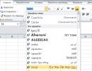
The Quick Select item corresponds to the QSELECT command and calls up the Quick Select dialog box of the same name (Fig. 3.16), which allows you to more precisely (by color, line type, layer, etc.) select objects for inclusion in a new or current set or removal from a selection set. The resulting set of objects will be used in subsequent editing commands.

Rice. 3.16. Quick Select Dialog Box
The Quick Select dialog box structure allows you to create an object selection equation with operations such as = Equals,<>Not Equal (<>Not equal), > Greater than (> More),< Less than (< Меньше), Select All (Выбрать все). Нужная операция устанавливается в раскрывающемся списке Operator (Оператор). Кроме того, используются следующие поля:
- Apply to - specifies what to apply the operation to (Entire drawing, Current selection);
- Object type - contains a list of object types (Line, Polyline, etc.) of the whole picture or the current set;
- Multiple means that primitives of different types are marked;
- Properties - contains a list of properties by which you can perform a selection operation (Color, Layer. Linetype, Linetype scale, Plot style, Lineweight lines), Hyperlink (Hyperlink)); if the current set already contains some objects, then the list may additionally contain properties of objects of specific types (Area, Closed, Thickness, Global width, etc.); The properties of objects are described in the next chapter:
Value - the value by which objects will be selected; the list of values depends on the type of property selected (for example, for the Color property it is a list of colors). The How to apply area using the Include in new selection set and(Exclude from new set) allows you to either add objects selected by this equation to a new set, or, based on a given criterion, exclude primitives from the created set. The primitives of the created set are attached to the current set if you select the checkbox Append to current selection set(Add to current set).
The next Find item in the context menu (see Figure 3.15) corresponds to the FIND command and brings up the Find and Replace dialog box, which allows you to find (and possibly replace) a string in text primitives, callouts, etc.
A group of menu items is dedicated to traditional work with the Windows operating system buffer, into which you can temporarily place objects and then paste them into a new location in the same drawing or into another file (let me remind you that AutoCAD 2004 allows you to open several drawings at the same time). The Cut item corresponds to the CUTCLIP command (VBU-FER) - cuts (removes) an object from the drawing and places it in the buffer. The Soru (Copy) item, corresponding to the COPYCLIP (KBU-FER) command, copies the object to the clipboard, but does not delete it from the picture. The Copy with Base Point option also corresponds to the COPYCLIP command, but allows you to further specify the insertion point (in the previous case, it is usually located in the lower left corner of the image). The Paste item corresponds to the PASTECLIP command for pasting an object from the buffer. The Paste as Block option also pastes an object from the buffer, but it is designed as a block paste. Paragraph Paste to Original Coordinates(Paste with original coordinates) allows you to transfer an object from the buffer to a new file, but in the same coordinate system as in the file from which it was extracted (coordinate systems are studied in Section 9.1). The operations of inserting files and blocks and the influence of the base point are discussed in detail in Section. 7.1.
The Tools drop-down menu contains an Options item that is used to configure a number of AutoCAD system features. Its operation is similar to calling the OPTIONS command from the command line or selecting Options from the right-click context menu when the mouse pointer is in the command line area and there are no selected objects. The OPTIONS command is discussed in more detail in Chapter. II, and at this moment the important thing is that it brings up the Options dialog box, which has a number of tabs and in particular the Selection tab (Fig. 3.17).

Rice. 3.17. Options Dialog Box, Selection Tab
In the Pickbox Size and Grip Size areas, you can change the size of the square crosshair that the system displays in object selection mode and the size of the grips, respectively.
The Grips area of the tab is dedicated to customizing grips. First, you can disable the grips tool altogether by unchecking the Enable grips checkbox. Secondly, you can set the colors of the unselected and selected grips to suit your needs using the corresponding drop-down lists: Unselected grip color, Selected grip color and Hover grip color. The last of these lists is an innovation that appeared only in AutoCAD 2004 due to the fact that when the cursor passes over a handle, it changes its color (green by default).
Handles are also used to pre-select objects for general editing operations such as erasing, copying, moving, etc. If objects have not been previously selected, then editing commands will prompt you to select objects. The selected objects form a so-called set, i.e. a subset of the objects in the drawing. You can add other objects to the set, or you can exclude objects from it (for example, using the Quick Select dialog box (see Figure 3.16)).
In Sect. 2.5 we have already considered the issue of selecting objects in three ways: direct indication, a regular frame and a secant frame. If you mark objects in response to the Command: command, then in fact this will mean executing a SELECT command, forming a set of objects with which some actions will be performed, determined during the execution of the next command. The SELECT command itself can also be entered using the keyboard and will issue a repeating prompt (the prompt repeats in a loop until a key is pressed).
Select objects:
There are many options to choose from. To get a hint listing these options, you need to enter the "?" sign on your keyboard. (by clicking, of course, after it
Expects a point or Window/Last/Crossing/BOX/ALL/ Fence/WPolygon/CPolygon/Group/Add/Remove/ Multiple/Previous/Undo/AUto/Single Select objects:(Requires point or Frame/Last/Secondary/BOX/All/Line/RMn-angle/SMn-angle/Group/Add/"Exclude/Multiple/Current/Cancel/Auto/Single Select objects:)
You must select a point using the mouse or enter one of the selection options. If, when specifying a point with the mouse, the square target (sight) falls on the line of some object, then it is selected and highlighted. If there are no object lines inside the target, then the specified point becomes the first point of the selection frame and the following request is issued:
Opposite corner:
The second point you specify at this moment becomes the second corner of the frame, and the frame is simple (i.e. selects only objects that fall inside the frame), if the second point of the frame was specified to the right of the first, and a secant frame (i.e. selects and objects that fall inside the frame, and objects crossed by the frame) - if the second point is indicated to the left of the first. Let's look at the selection options:
- Window (Frame) - allows the two points indicated below to be considered the corners of a regular frame, regardless of their location;
- Last - selects the last constructed object from those visible on the screen;
- Crossing - allows the two points indicated below to be considered the corners of the secant frame, regardless of their location;
- BOX (BOX) - goes into the mode of specifying a frame, which becomes normal or secant depending on the location of the corners of the frame;
- ALL (All) - selects all unfrozen objects of the drawing (for freezing layers, see section 4.3)",
- Fence (Line) - allows you to build an open (open) polyline and the objects crossed by it are included in the set;
- WPolygon (PMn-angle) - builds an analogue of a frame in the form of a closed polygon, and only those objects that fall inside it are selected;
- CPolygon (CMn-angle) - is an analogue of a secant frame, but the frame has the shape of a polygon;
- Group - selects a group (a set with a name, previously formed using the GROUP command);
- Add - allows you to switch to the mode of adding objects to the set (completes the mode of excluding objects from the set);
- Remove - goes into the mode of excluding objects from the set (completes the mode of adding objects to the set);
- Multiple (Several) - does not highlight objects when they are selected, thereby speeding up the work;
- Previous (Current) - allows you to take as a set the set generated by the AutoCAD system the previous time;
- Undo - undoes the last operation of adding an object to the set or removing it;
- AUto - enters automatic selection mode. Moreover, if an object hits the sight at the point of reference, it is selected. Otherwise, the entered point becomes the first corner of a regular or secant frame, i.e., the BOX mode is activated;
- Single - allows you to switch to the mode of selecting a single object that is on the target of the pointing device. Once the first object is found, the selection operation stops.
AUto and Add modes are the default.
If the set of primitives generated as a result of selection operations is needed in further work with the drawing, then such a set should be formatted as a group, which is saved inside the drawing file and is available in subsequent editing sessions. To create groups, use the GROUP command, which must be entered from the keyboard.
The GROUP command opens the Object Grouping dialog box (Figure 3.18).

Rice. 3.18. Object Grouping Dialog Box
At the top of the window there is a list of groups already existing in the drawing file (in Fig. 3.18 this is a group named G1). The list has two columns: Group Name and Selectable. The first of them contains group names (up to 31 characters long, names can use letters and numbers, as well as the symbols $, - (hyphen) and _ (underscore); spaces are not allowed), and the second contains the selectable™ parameter, which can only take two values: Yes or No. In the list of groups, names are arranged alphabetically.
A group is called selectable if, when you select any element of the group, the AutoCAD system immediately highlights all other elements of the group located on unfrozen and unblocked layers.
The first time you open the Object Grouping window, the list of groups is still empty. To create a group, in the Group Identification area, enter a name in the Group Name field and fill in the Description field. Then, in the Create Group area, select or clear the Selectable checkbox and click the New button. AutoCAD will temporarily close the Object Grouping window and prompt you to specify the objects that will be included in the group being created. The end of object selection will be pressing the key
As soon as a group is created, its name will immediately appear in the general list of groups at the top of the window.
You can create unnamed groups. To do this, before clicking the New button, you must select the Unnamed checkbox in the Create Group area. If the user creates groups without a name, the system itself assigns names to such groups (*A1, *A2, *AZ, etc.). To include unnamed group names in the Group Name list, you must select the Include Unnamed check box in the Group Identification area.
The Group Identification area contains two additional buttons. The Find Name button allows you to find the names of all groups to which the primitive belongs. The system temporarily closes the Object Grouping dialog box and asks you to specify a single object:
Pick a member of group:
After you have specified an object, the system opens the Group Member List window (Figure 3.19), which provides a list of all the groups to which the selected object belongs.

Rice. 3.19. Group Member List Window
The Highlight button of the Object Grouping dialog box (see Fig. 3.18) allows you to highlight all the primitives included in the group whose name is marked in the general list of groups.
The Change Group area is available if a group name is selected in the general list. The buttons in this section allow you to change any property of the group:
- Remove - excludes objects from the selected group;
- Add - adding objects to the selected group;
- Rename - replaces the group name with the current contents of the Group Name field in the Group Identification area;
- Re-Order - changing the order of objects within a group;
- Description - replaces the explanation for the group with the current contents of the Description field in the Group Identification area;
- Explode - deleting a group from the list of groups (the objects themselves that were part of the group are not deleted from the picture);
- Selectable - Changes the selectable™ property of the group.
The Re-Order button opens the Order Group dialog box (Fig. 3.20), in which you can change the serial numbers of objects in the selected group.
By default, object numbers start at 0 and correspond to the order in which they were selected when included in the group. In special uses of groups, the sequence of objects within a group can be important (for example, in the case of a tool path).
Using the buttons in the window shown in Fig. 3.20, you can either change the serial numbers of individual elements (either one at a time or for several), or reverse the order of all elements.

Rice. 3.20. Order Group Window
In order to find out the order of objects in a group, you need to click on the Highlight button. The Order Group window will temporarily close and the Object Grouping window will appear. At this moment, only object number 0 will be highlighted in the figure. Clicking the Next button will extinguish object number 0 and cause only object number 1 to be highlighted. Information about the number of the highlighted primitive is displayed in the bottom line of the window (Fig. 3.21).

Rice. 3.21. Object Grouping Window
Using the Next and Previous buttons, you can go through all the primitives included in the group and determine their serial numbers. Clicking OK will take you back to the Order Group window.
The Reverse Order button in the Order Group window reverses the order of objects.
In order to move an object to a new location, you must indicate its number in the Remove from position field, and in the Enter new position number for the object(Move to position) - new number.
If you have created groups in your drawing, you can select objects from the entire group at once when prompted by the SELECT command by selecting the Group option and entering the name of that group in response to the next prompt.
Computer-aided design systems - CAD
Working in AutoCAD
Self-instruction manual
5.3.5. Changing object properties using the Properties palette
All we have to do is modify the two inner circles to bring their diameters in accordance with Fig. 5.36.
1. Click on the inner circle to select it. Squares called selection handles will appear in the center and at the points of the quadrants.
2. Click the button Properties Standard toolbar (this button is to the right of the Window Zoom previous). A palette will appear on the left side of the AutoCAD window Properties, which can be dragged by the vertical header to any place on the screen, as shown in Fig. 5.40.

Rice. 5.40 Palette Properties allows you to view and change the properties of the selected object
3. As can be seen from Fig. 5.40, at the top of the palette Properties there is a drop-down list that displays the type of selected object (in this case - Circle). Find in the section Geometry palettes Properties element Radius and click on its value, and then enter 30 (see Figure 5.36) instead of the current value of 25.
4. As soon as you press Enter, the radius of the selected circle in the drawing will immediately change, as a result of which it will become not the smallest, but the middle one.
5. Press Esc to deselect (in the palette drop-down list Properties a message will appear No set), and then click on the circle that is now the smallest.
6. Click on the element value Radius palettes Properties and enter 32 instead of the current value of 27. The diameter of the selected circle will increase, causing it to become the middle circle again instead of the inner circle.
7. Click on the close button of the palette Properties to remove it from the screen.
8. Restore the previous scale using the tool Zoom previous.
Note. Palette Properties is a convenient tool that, as you have just seen, makes working with drawing objects much easier. We'll be using this palette a lot in subsequent chapters, so we'll come back to discuss it in more detail.
Any, even the most complex, drawing consists of a collection of elementary objects that can be created using one command. This includes segments, circles, arcs and other graphic objects. In AutoCAD, such objects are called graphic primitives. To place an object in the drawing window, call the corresponding command, specify the coordinates of the points and the necessary parameters. In this lesson we will look at commands designed to create graphic primitives.
Point
Command entry methods:
Enter the command using one of the following methods.
A point in the drawing window is specified by coordinates that are entered from the keyboard or fixed by pressing LMB on the work field in response to a system request
Current point modes: PDMODE=0 PDSIZE=0.0000
Specify a point:
You can set the size and shape of a point. The size is specified in absolute units or relative to the screen size.
The point type and size can be selected in the dialog box. The window is called by the command Format>Point Style.

Line
Command entry methods:
In order to construct a segment, you need to specify the coordinates of two points - the start and end. The command builds a single segment or a sequence of segments. When constructing a sequence of segments, the end point of the previous segment is the starting point for the next one.
- Upon system request Specify first point:
- When prompted by the system, enter the coordinates of the starting point.
- Upon system request Specify next point or:
- terminate the command by pressing a key Enter;
- Upon system request Specify next point or: do one of the following:
- enter the coordinates of the end point of the next segment;
- terminate the command in one of the following ways:
- pressing a key Enter;
- enter option Close from the keyboard. In this case, a segment is constructed that connects the last point with the starting point of the first segment. Thus, a closed loop will be built;
- if you have not completed the command, then the fifth step is repeated the required number of times.
Circle
Command entry methods:
- Call from the menu: Draw>Circle
- Toolbar button

A circle can be constructed in the following ways:
- Specify the center of the circle and the size of the radius or diameter.
- Indicate the coordinates of three points that lie on the circle and do not lie on the same straight line.
- Specify the coordinates of two points that are the ends of the diameter.
- Construct a circle that touches two previously constructed objects at the specified points.
To build, you must perform the following sequence:
- Enter the command using one of the methods listed above
- Upon system request circle Specify center point for circle or : choose one of the methods for constructing a circle.
1 way
- Enter the coordinates of the circle center.
- Upon system request Specify radius of circle or: Enter radius values or option D.
- If you entered option D, you will be prompted Specify diameter of circle, where you need to enter the diameter value.
It is worth noting that when the system asks you to specify a radius or diameter, you can specify not the corresponding value, but the coordinates of the point. After which the program will independently calculate the radius or diameter from a given point to the center of the circle.
Method 2
- Enter the 3P option, which corresponds to the choice of the method for constructing a circle using three points.
- Next, enter or specify the coordinates of three points one by one.
3 way
- Enter the 2P option, which corresponds to the choice of the construction method based on the end points of the diameter.
- Enter or specify the coordinates of two points.
4 way
- Enter the Ttr option. In this case, the circle comes into contact at two points with the objects constructed earlier.
- Specify or enter the coordinates of two points
- Enter the radius of the circle or press the key Enter. In this case, the radius will be calculated automatically.
Arc
Command entry methods:
- Type commands from the keyboard: Arc
- Call from the menu: Draw>Arc
- Toolbar button

The arc is constructed in eleven ways, which differ in the choice and combination of three parameters:
Start- starting point;
Center– center of the arc;
End– end point;
Angle– central angle;
Chord Length – chord length;
Direction– direction of the tangent (indicated by one point and coincides with the vector drawn to this point from the starting point);
Radius– arc radius;
3 Points– at three points lying on the arc;
Continue– construction of an arc as a continuation of the previous line or arc. The starting point and starting direction, respectively, will be the ending point and ending direction of the previous arc or segment.
Construction line (Xline)
Command entry methods:
The construction line is a ray directed in both directions from a given point.
To build, you must perform the following sequence:
- Enter the command using one of the methods listed above.
- Upon system request Command: _xline Specify a point or : choose one of the construction methods:
1 way
- Enter the coordinates of the first point.
- Enter the coordinates of the second point.
- Upon system request Specify through point: enter the coordinates of points to construct several construction lines for which the starting point will be common, or complete the command by pressing the key ESC or ENTER.
Method 2
- Enter the Hor or Ver parameter, which allows you to construct a construction line parallel to the X or Y axis.
- Upon system request Specify through point: enter the coordinates of the point. Continuing to indicate the coordinates of points to the request Specify through point:, you can build several parallel lines.
3 way
- Enter parameter Ang, which allows you to build a construction line at a certain angle to the X axis or relative to a specified straight line.
- Upon system request Enter angle of xline (0) or :
- Enter the angle value in degrees to construct a straight line at an angle to the X axis and at the system request Specify through point: enter the coordinates of the point through which the construction line will pass.
- Enter parameter R, to construct a straight line at an angle to another straight line and to the request Select a line object: point to a straight object with the cursor. Next will be a request to indicate the angle ( Enter angle of xline<0>: ) and points ( Specify through point:), through which the line will pass.
4 way
- Enter parameter Bisect, which allows you to construct the bisector of an angle.
- Consistently indicate the vertex point of the corner and side in response to the system request.
5 way
- Enter parameter Offset, which allows you to build a construction line parallel to the specified line.
- Sequentially specify the offset, line, and offset direction in response to the system prompt.
Ray
Command entry methods:
Ray is a line directed from a point to infinity. It is specified by two points - the starting point and the point lying on the ray.
Polyline
Command entry methods:
Polyline consists of sequential connections of lines and arc segments. Each segment can have a specific width. The width value at the start point of a segment may be different from the value at the end point.
When constructing a polyline, it is necessary to determine the starting point in response to a system request Specify start point: Next, the following options become available:
Halfwidth– Sets half the width of the polyline segment at the start and end points.
Width– Sets the width of the polyline segment at the start and end points.
Lenght– creates a polyline segment of a given length in the same direction as the previous one.
Arc– creation of an arc segment of a polyline.
Close– connects the end point of a polyline to the starting, straight segment.
Undo– the last constructed segment is deleted.
In arc construction mode, the following parameters become available:
Angle– central angle;
Center- center;
Close– connects the end point of a polyline with its beginning with an arc segment;
Direction– tangent direction;
Line– transition to the mode of constructing straight line segments;
Radius– arc radius;
Second pt– intermediate point on the arc;
Polyline built by the command Pline is treated as a single object in AutoCAD. Editing a polyline is done with the command PEDIT. Team EXPLODE a polyline can be split into individual elements. Editing polylines will be described in more detail in the following lessons.

Polygon
Command entry methods:
The command constructs a regular polygon with a given number of sides.
You must specify the construction method:
- The polygon describes ( Circumscribed) circle for which the radius is specified;
The dialogue looks like this:
<9>:7
- Inscribed polygon ( Inscribed) into a circle for which the radius is specified;
The dialogue looks like this:
Command:_polygon Enter number of sides<7>:7
Specify center of polygon or :300,300
Enter an option
Specify radius of circle: 50
- The length of the side is specified ( Edge) and coordinates of the end points of this side;
A polygon is a polyline, so to edit it you can use the same commands as for editing polylines.

Rectangular
Command entry methods:
To construct a rectangle, you need to specify the coordinates of two diagonally opposite vertices.
The dialogue looks like this:
Command:_rectang
Specify first corner point or :100,100
Specify other corner point or :300,300
Command parameters:
Area– construction of a rectangle with a given area;
Dimension– construction of a rectangle of a given length and width;
Rotation– rotation of the rectangle at a given angle relative to the X axis;
Ring (Donut)
Command entry methods:
A ring is a part of the plane between the outer and inner concentric circles. The thickness of the ring is equal to half the difference in the diameters of these circles. Rings are solid filled objects.
After entering the command, the system issues a request for the size of the internal and external diameters, and also requests the position of the center of the ring.
The dialogue looks like this:
Specify inside diameter of donut<0.5000>:150
Specify outside diameter of donut<1.0000>:250
Specify center of donut or

Spline
Command entry methods:
A spline is a smooth curve that passes through a given set of points. When constructing a spline, the position of the points and the direction of the tangents at the start and end points are taken into account.
After entering the command, the system prompts you to enter the coordinates of the points or enter the key. The last two requests for entering the tangents of the tangent angles at the start and end points.
The dialogue looks like this:
Command:_spline
Specify first point or:100,200
Specify next point:310,110
Specify next point or
Specify next point or
Specify next point or
Specify next point or
Specify start tangent:10
Specify end tangent:20
Command parameters:
Object– converting a smooth line into an equivalent spline.
Close– closes the curve by connecting the last point to the first.
Fit Tolerance(Tolerance) – sets the accuracy of the spline approximation. If set to 0 (Default), the spline passes exactly through the specified points. The higher the value, the more the spline deviates from the specified points and becomes smoother.

Ellipse
Command entry methods:
- Type commands from the keyboard: Ellipse
- Call from the menu: Draw>Ellipse
- Toolbar button

An ellipse can be constructed by specifying the center and radius of an isometric circle, or by specifying the start and end points of one axis and the distance from the center of the ellipse to the end of another axis.
Keys:
Axis endpoint– end point of the axis. When this option is selected (it is set by default), two end points of the first axis and a point are specified that indicates the distance from the center of the ellipse to the end of the other axis.
Rotation– an ellipse is constructed as a projection of a circle that rotates around a diameter determined by previously specified points on the drawing plane. Range of permissible angles ()…89.4.
Center– center of the ellipse. It is also necessary to specify the coordinates of the end point of the axis and the distance from the center to the end point of the other axis.
Arc— allows you to build an elliptical arc.
Dialogue when using the key Axis endpoint:
Command:_ellipse
Specify axis endpoint of ellipse or :120,200
Specify other endpoint of axis:820,600
Specify distance to other axis or :550,260 has the form:
If you select the key Center, the dialogue will be like this:
Specify axis endpoint of ellipse or :c
Specify center of ellipse:470,400
Specify endpoint of axis:470,870
Specify distance to other axis or :600,400
Cloud (Revision cloud)
Command entry methods:
Cloud is a closed polyline designed to highlight notes and changes made to the drawing.
After entering the command, information is entered with default settings (minimum arc length: 15, maximum arc length: 15;) and a request is issued to enter the starting point.
Command:_revcloud
Minimum arc length:15 Maximum arc length:15
Specify start point or
Guide crosshairs along the cloud path…
After this request, the user can use the cursor to indicate the starting point, and then use the cursor to draw a free-form cloud. Once the loop is closed, the command ends.
You can build a non-closed cloud by right-clicking on the last point.
Command keys:
Arc length– set the length of the arc;
Object– allows you to give the shape of a cloud to a graphic primitive;

It is worth noting that in the latest versions of AutoCAD, which already have a dynamic input system, the user is given the opportunity to select additional options when creating a primitive from a drop-down list called by right-clicking. The system will also automatically display a window asking you to enter mandatory options, the parameters of which are necessary to complete the command.
This lesson shows all the two-dimensional graphic primitives available in the AutoCAD system. How to work with primitives after their construction, as well as how to edit them to create more complex objects, will be described in.
AutoCAD software package is a system that allows you to automate drawing and graphic work. AutoCAD is a software package from Autodesk that is computer-aided design system (CAD). The main advantage of AutoCAD is the availability of creating powerful specialized calculation and graphic packages on its basis. The AutoCAD system allows the development of two-dimensional drawings and drawings, as well as surface and volumetric (solid-state) structures in various fields of human activity (engineering, construction and architecture, etc.). This manual will discuss the AutoCAD 2007 package. All versions of the AutoCAD system are interconnected by a single data storage format and are designed to work in the Microsoft Windows operating system (starting with the Microsoft Windows 95 operating system). The main advantage of the AutoCAD system is the possibility of subsequent generation of an electronic archive of drawings. Each of the files and drawings created in this way can be easily edited, which allows you to quickly obtain analogue drawings from prototype drawings. To facilitate the process of issuing design documentation, “libraries of standard elements” can be developed. Both entire files and their individual parts can serve as standard elements. Starting with AutoCAD 2002, the system includes special tools to control enterprise standards, allowing you to manage layers, styles, etc. A powerful addition to this is the ability to use programming languages. The AutoCAD system has a built-in AUTOLISP language compiler, which allows the user to expand the capabilities of the system, as well as application development tools in the C programming language. The AutoCAD 2007 software package allows you to work simultaneously with several drawings, has powerful visualization tools for created three-dimensional objects and advanced capabilities for adapting the system to requirements the user, providing connection of graphic objects with external databases, allows you to view and copy drawing components without opening its file, edit external links and blocks located in external files, and much more. Computer requirements vary depending on the software version. With each later version of AutoCAD, the computer requirements become more stringent. So, for AutoCAD 2000 you need a processor no worse than Pentium 133 Mhz, the recommended amount of memory is 64 Mb (minimum is 32 Mb), hard drive is at least 130 Mb of free space, 50 Mb of free disk space in the system directory, at least 64 Mb in swap file. The design system itself takes up about 150 – 190 Mb (depending on the installation option). You must have a mouse and an SVGA monitor with a resolution of at least 800x600. For AutoCAD 2007, you need a computer with at least a Pentium III 800 Mhz (preferably a Pentium IV), a memory capacity of at least 256 Mb (better than 512 Mb), and a hard drive of at least 2 Gb. The recommended operating systems are Microsoft Windows 2000 (SP4) and Microsoft Windows XP (SP2).
Manual drawing tools in an automated environment correspond to graphic primitives (point, segment, circle, etc.), commands for editing them (erasing, transferring, copying, etc.), commands for setting the properties of the primitive (setting the thickness, type and color of graphic objects) . To select a sheet of the desired format and scale of the drawing, the system has appropriate configuration commands. To apply a dimension, you only need to specify its location in the drawing. Dimension and extension lines, as well as arrows and inscriptions are performed automatically.
AutoCAD commands allow you to enlarge or reduce the image of a drawing on the screen if necessary, as well as move the boundaries of the part of the drawing visible on the screen without changing the image scale.
The system provides the ability to combine graphic objects into a single block, which is stored under a specific name and, if necessary, inserted into any drawing. It is possible to create images of individual drawing elements or individual assembly parts on different layers. This allows you to control the compatibility of parts during layout. By turning layers on or off, you can add or remove parts from the overall layout, thereby creating convenience in selecting different product design options. It is useful to use layers even in simple drawings, placing a drawing blank, outline, dimensions, inscriptions, centerlines on each separate layer, for the subsequent ability to quickly select a group of objects and edit them.
In addition to creating 2D drawings, AutoCAD can model 3D objects and give 3D drawings a photographic reality.
Basic terms. AutoCAD commands are formed in the process of accessing menus and toolbars and represent a certain sequence of subcommands that are selected in each subsequent submenu. Calling commands and entering graphic elements is carried out using a mouse or keyboard.
Terms used to describe a mouse in AutoCAD:
· cursor– mouse pointer on the screen (the appearance of the cursor can change, taking the form of either a crosshair, or a small square (sight), or an arrow, or a hand);
· aim– a small square used when selecting objects in the graphic area;
· indicate– move the cursor to the graphic object and click the left mouse button;
· choose– move the cursor in the shape of an arrow and click on a menu item, toolbar icon or dialog box control;
· click– press and quickly release the mouse button (usually the left one);
· double click– quickly perform two clicks;
· stretch out– move the cursor followed by the graphic object;
· click and drag– press the left mouse button and, without releasing it, move the cursor, behind which the selected object will move across the screen.
Login to the AutoCAD environment. Launching AutoCAD in the Microsoft Windows operating environment is carried out, for example, with the command Start → All Programs → AutoCAD → AutoCAD 2007 (Start → Programs → AutoCAD → AutoCAD 2007).
After loading, a dialog box will appear on the screen. There are 2 types displayed in the main menu bar Workspace:
· 3D Modeling(a new type of space optimized for 3D modeling);
· AutoCAD Classic(classic workplace).
After selecting the workspace type, a graphical user interface ( Graphical User Interface - GUI) (Fig. 2.1):
Rice. 2.1. AutoCAD 2007 graphical user interface
Graphical interface. There are four functional areas on the screen:
· Working graphic area– a large area in the middle of the screen where the drawing is done. In the lower left corner of the zone there is an icon for the user coordinate system. The directions of the arrows coincide with the positive direction of the axes.
· System menu and toolbars. At the very top of the screen there is a title bar with the file name (by default Drawing1). Immediately below it is the AutoCAD system menu bar. Below are two lines occupied by toolbars. To the left of the working area there are “floating panels” of tools Draw And Modify. They can be moved anywhere on the screen. Other panels are called as needed.
· Command line. Below the graphical work area is the command line. You can launch any AutoCAD command by typing its name at the command line. If a command is launched via a toolbar icon or menu item, the command line also displays the system's response to the corresponding command. In addition, everything you enter from the keyboard immediately appears on the command line. Any command is initiated only after the previous one has completed. There should be a command prompt on the command line Command. You can cancel any action by pressing the key on the keyboard Esc.
· Status bar. The status bar displays the coordinates of the crosshair, which changes as you move the crosshair with the mouse.
1. Click on File in the top line of the standard toolbar, then select from the list Save as. A dialog box will appear on the screen Save Drawing As with a list of all folders on the selected disk.
2. In the top line of the window Save in: (Folder:) you need to set the name of the created folder. To do this, select the desired folder from all of the above and double-click on it.
3. In the field File Name you should enter a name for the drawing, for example Drawing1, and press Enter or click on the button Save.
Sign Out. You can use one of the following to log out:
· click on the button Close– a cross in the upper right corner of the screen;
· type the word in the command line Quit and press Enter;
· select from the menu File → Exit.
If the information in the drawing has not been saved, AutoCAD will prompt you to save it. You can accept this offer by answering Yes, you can log out without saving recent changes by replying No, and refuse to exit and return to the drawing by pressing Cancel.
Menus and toolbars. AutoCAD commands are called from the menu or using toolbar icons. The system menu bar in AutoCAD consists of the following drop-down menus:
· File– the menu is intended for opening, saving, printing, exporting to other file formats (drawings), as well as exiting the system;
· Edit– menu for editing parts of the drawing in the work area;
· View– menu for controlling the screen, switching paper and model space modes, setting the point of view for three-dimensional models, toning, managing display parameters;
· Insert– a menu of commands for inserting blocks and objects from other applications;
· Format– menu for setting drawing boundaries and units of measurement, managing text style, dimensions, working with layers, color, line type and thickness;
· Tools– menu of system control tools, setting drawing parameters, bindings and user coordinate system;
· Draw– menu of graphic primitives;
· Dimension– menu of commands for applying dimensions;
· Modify– menu for editing graphic objects;
· Window– standard Windows menu for managing and sorting open drawings (files);
· Help– help menu;
· Express–optional menu during full installation for quick access to commands.
The standard toolbar contains the following tools:
· QNew (Quick New Project)– quickly create a new file;
· Open… (Opening)– open an existing file;
· Plot… (Print)– output the drawing to a printer;
· Plot Preview– preview of the drawing before printing, allowing you to see the placement of the drawing on a sheet of paper;
· 3DDWF– load the interface for publishing 3D DWF projects;
· Cut– delete selected drawing elements to the Microsoft Windows buffer;
· Copy– copy selected drawing elements to the Windows clipboard;
· Paste– insert data from the Microsoft Windows buffer;
· Match Properties– assign properties of a given object to another object;
· Block Editor– calls up a menu of available blocks in the drawing;
· Undo– cancel the last action;
· Redo (Repetition)– restore the just canceled action;
· Pan Realtime– move the drawing relative to the point;
· Zoom Realtime– scale the drawing relative to the point;
· Zoom Window– scale the drawing within the window selected by the user’s mouse;
· Zoom Previous– returns to the overview of the previous zoom;
· Properties– opens drawing properties;
· DesignCenter– opens the built-in library of drawing elements;
· Tool Palettes Window– turns on/off the display of the palette window on the workspace;
· Sheet Set Manager– opens the scheme manager;
· Markup Set Manager– opens the drawing layout manager;
· QuickCalc (Quick calculator)– calls up the calculator;
· Help– opens a certificate;
· Layer Properties Manager– opens the layer properties manager. A little to the right are the main commands for layers - turn a layer on/off, lock/move a layer from all points, lock/move a layer from a specific point and select a color for a layer.
To work with the AutoCAD editor, commands are used, which can be entered in various ways: typed on the keyboard, selected from a menu, or clicked on the corresponding icon on the toolbar. The command can only be entered at the moment when the prompt is displayed in the command line window Command:. To enter a command from the keyboard, type the command name and press Enter. You can enter an abbreviation for those commands for which it is defined. Yes, for the team Circle you can enter WITH. Commands can be entered using toolbars. Toolbars can be either floating or docked, with a fixed location. Floating panels can move around the graphic field and change size; docked panels cannot change size and overlap the graphic field. A floating panel can become docked if you move it outside the graphics area. A docked panel turns into a floating panel as soon as it moves into the graphics field area. A tool button may have a small triangle in the lower right corner. If you press the left mouse button when specifying such a tool and do not release it for a while, a toolbar will appear containing various options for executing the selected command. After entering the command, AutoCAD issues prompts in response to which you must enter additional information: a numerical value (for example, distance, angle, etc.), a keyword, or a point; or brings up a dialog box. Some commands allow both the command line and a dialog box.
The system reacts to a particular menu item in the following way:
· displays a submenu if there is a black triangle on the right;
· opens a dialog box if the item ends with an ellipsis;
· executes the command in other cases.
Working with coordinates. When AutoCAD prompts for a point, it expects the coordinates of some point in the current drawing to be entered. After specifying a point, a small marker may appear in its place for better orientation, which disappears after regeneration or redrawing.
Entering coordinates in AutoCAD can be done in two ways: directly from the keyboard by specifying numerical values and using a graphic marker (cursor), which moves across the screen using a pointing device. Coordinates are entered by pressing the left mouse button. The status bar displays the current coordinates.
Numeric values can be: whole, real, specified in decimal format, in exponential form, And as fractions. The numerator and denominator of the fraction must be integers, and the denominator must be greater than the numerator. Numerical values in AutoCAD specify conventional units. A conventional unit can correspond to any units of measurement of length: meters, inches, feet, centimeters, angstroms, etc. Thus, when drawing, you can operate with real dimensions without thinking about scaling. The finished drawing can be drawn to any given scale.
In two-dimensional space, a point is defined in a plane XY, which is called construction plane. Coordinate input from the keyboard is possible in the form of absolute and relative coordinates. Absolute coordinates can be entered in the following formats: rectangular coordinates X, Y and polar coordinates r< А , Where r– radius and A– angle from the previous point. The angle is specified in degrees counterclockwise. Relative coordinates specify the offset from the last entered point. When entering points in relative coordinates, you can use any recording format in absolute coordinates: @dx,dy– for rectangular, @r< А – for polar ones.
Coordinate values, regardless of the input method, are always associated with some coordinate system. By default, AutoCAD uses the so-called world coordinate system (WCS) (WCS). It is defined so that the axis OH directed from left to right, axis OY– from bottom to top, axis OZ– perpendicular to the screen outside.
For convenience, it can be defined user coordinate system (UCS) (UCS), which can be shifted relative to the world one and rotated at any angle.
AutoCAD has the ability to set line drawing modes. This polar mode, in which lines are drawn at different angles, and orthogonal, in which lines are drawn only along the coordinate axes. Switching modes is done by pressing the key on the keyboard F8 or by clicking on the command button Ortho Mode in the status bar.
To accurately enter the coordinates of points using the mouse, AutoCAD has special commands:
· step binding SNAP– mode of mouse pointer movement with a certain step, which is not necessarily equal to the step of an imaginary grid (the grid can be made visible using the command Grid);
object snap OSNAP– mode of binding coordinates to various points of already created objects.
You can enable or disable these modes using the corresponding command buttons on the status bar. You can adjust the binding characteristics in the dialog box Tools → Drafting Settings…, by setting the appropriate bookmark, or select the corresponding command buttons in the status bar, right-click and select the option Settings...:
· Snap and Grid– to set snap and grid parameters (Fig. 2.2):
Rice. 2.2. Drafting Settings Dialog Box, Snap and Grid Tab
· Object Snap– to set object snap parameters (Fig. 2.3);
Rice. 2.3. Drafting Settings Dialog Box, Object Snap Tab
Geometric elements of the drawing. Any drawing consists of sections of geometric elements (graphic primitives), for example, straight and curved lines. Tools are used to draw straight sections of a drawing. Line, Construction Line, Multiline, Polyline, Polygon And Rectangle. Curvilinear sections are created by tools Arc, Circle, Spline, Ellipse, Hatch... (Hatching...) and others.
The specified tools correspond to certain commands for drawing the corresponding primitives. A description of these commands is given below in the order of the icons (from left to right) on the toolbar Draw(Fig. 2.4).
Rice. 2.4. Draw toolbar
Command _line (Line). Team _line belongs to a group of commands that are repeated an arbitrary number of times until a key is pressed Enter. It has two options that can be selected from the command's context menu while constructing line segments or by entering a capital letter from the keyboard:
· Undo (Return)– erases the last formed segment of the polyline without completing the command;
· Close– automatically draws the last segment, closing the line (the option appears only after the second drawn segment).
Command _xline (Construction line). Team _xline serves to draw auxiliary lines that can be used, for example, as communication lines between projections of a part. The difference between this primitive and a simple line is that it is automatically extended in both directions to the borders of the screen, regardless of the image scale.
Team _xline has five options:
· Hor– to construct horizontal lines ;
· Ver– for constructing vertical lines ;
· Ang– for constructing inclined lines at a certain angle, the value of which is entered from the keyboard at the corresponding command request ;
· Bisect– to construct the bisector of an angle from its vertex and two points located on the sides of the angle ;
· Offset– to construct a straight line parallel to any specified segment at a specified distance or through a specified point .
Team _xline, starting with AutoCAD 2000, has lost its significance, since new versions have added the tracking function for object snapping (button Otrack in the status bar), allowing you to generate temporary auxiliary lines, instead of real geometric constructions.
Command _mline (Multiline). Team _mline builds a set of parallel (no more than 16) broken lines, which are called elements. The command has three options:
1. Justification (Location)– defines the position of the drawing point :
· Thor (Top)– the line passes with a maximum positive displacement from a given point;
· Zero (Center)– the line passes with zero displacement from a given point;
· Bottom– the line passes with a maximum negative displacement from a given point;
2. Scale– the number by which the offset between lines is multiplied, set in the multiline style ;
3. Style– selecting a style (the style name is entered from the keyboard), the style is loaded by default Standard, which allows you to draw a line consisting of two parallel lines .
To select options, you can use the context menu or type capital letters of the option names at the command prompt.
When specifying options from the keyboard, you must type the capital letters of the Latin alphabet marked on the command line. For example, to select the option Style you need to enter two letters from the keyboard - ST.
Command _pline (Broken line). Team _ pline allows you to build a sequence of straight and arc segments. On straight sections, the command allows you to change the width both when moving from one segment to another, and within one segment. The command has six options:
· Halfwidth– allows you to set the half-width (distance from the center line of the segment to the edge) ;
· Width– allows you to set the width of the subsequent segment (AutoCAD prompts you for the start and end width) ;
· Undo– cancels the last created segment ;
· Arc– switches the command to the mode of drawing arcs ;
· Close– closes the line with a segment ;
· Length– defines the next straight segment in the same direction as the previous one .
Command _polygon (Polygon). Team _polygon builds a regular polygon with the number of sides from 3 to 1024. After calling the command, in response to the system prompt, enter the number of sides of the polygon. Then you need to select one of three methods for defining a polygon, which correspond to the command options:
· Edge – determines the position of any polygon edge from two given points ;
· Inscribed in circle– forms an imaginary circle at a given center and radius into which the polygon will be inscribed ;
· Circumscribed– forms an imaginary circle at a given center and radius around which the polygon will be described.
The last two options appear after specifying the center of the circle.
Command _rectang (Rectangle). Team _rectang allows you to construct a rectangle using two opposite vertices. To specify vertices, you can use any method of entering coordinates. The rectangle can be defined with chamfers and rounded edges using the following options:
· Area– forms bevels at the corners when specifying the distances from the vertex to the bevel along both sides;
· Dimensions– forms rounding of corners when entering a fillet radius value;
· Rotation– sets the angle of rotation of the figure;
In addition to the listed options, the command contains three more options that can be used to form a parallelepiped with a rectangle at the base. However, most often this command is used to specify a rectangle in the plane XY.
Command _arc (Arc). Team _arc allows you to draw part of a circle. There are different ways to define an arc in AutoCAD. In Fig. 2.5 shows the command options that allow you to draw an arc in one way or another. Options are selected via submenus Arc menu Draw. Depending on the selected option, the arc can be drawn either in the first seven ways (drawing is done from the point of origin of the arc) or in the penultimate three (the beginning of drawing is the center of the arc). If you call the command using the icon, the system will prompt you to enter the starting point of the arc or its center. When selecting the option Continue you can draw an arc whose starting point will be the end point of the previous arc or segment. Moreover, the arc will go tangent to the previous element.
Rice. 2.5. _arc Command Options
It should be noted that arcs are constructed from the starting point counterclockwise, however, you can enter the value of the central angle and the length of the chord with a minus sign.
Command _circle (Circle). Team _circle allows you to draw a circle in one of six ways:
· By two points of diameter circles - options 2 Points (by 2 points);
· By three points on the circle– options 3 Points;
· By two tangents (two segments, a segment and a circle, etc.) and a radius– options TanTan Radius;
· By three tangents– options Tan Tan Radius.
Command options are selected from a submenu Circle menu Draw or during a dialogue from the command context menu (Fig. 2.6).
Rice. 2.6. _circle Command Options
Command _spline (Spline). Team _spline allows you to draw a wavy line in the drawing. Spline is built using points that are sequentially entered after calling the command. In order to finish constructing the spline, you need to right-click and select from the context menu Enter– press the left button, then press the right mouse button 2 times.
Command _ellipse (Ellipse). Team _ellipse allows you to draw both a complete ellipse and part of it. The main parameters of the ellipse are the coordinates of the center, the direction and size of the major and minor axes.
A complete ellipse can be drawn in two ways:
· determine the center of the ellipse, and then the remaining parameters - select an option Center;
· define the end points of the ellipse axes – select an option Axis, End.
An option is available to rotate the ellipse using the command Rotation. To construct part of an ellipse, you need to select the option Ellipse Arc.
Command _bhatch (Hatching). At shading areas bounded by a closed contour consisting of segments, circular arcs, etc. are filled. Hatching is characterized by 2 properties:
· shading is block;
· shading happens associated with an object (associative), i.e. when an object changes, it automatically adjusts to its shape, and unrelated (non-associative).
To create a hatch, click on the icon Hatch... (Hatching...) toolbars Draw or call a command from the drop-down menu with the same name.
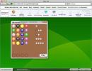
After running the command, the hatch dialog box appears on the screen (Fig. 2.7), in which you can:
· select the desired shading – window Ture (Type) install "User defined";
· determine the part of the drawing that needs to be shaded - buttons Pick Points And ;
· set hatching parameters – list windows Angle And Scale;
· preview the hatching before displaying it – button Preview.
Rice. 2.7. Hatch Dialog Box
Define The area for hatching can be done in two ways: specify a point inside the area (click with the mouse) or select objects that limit the area. In the first case, you need to press the button Pick Points, and in the second – a button Select objects.
To create multiple contours, after specifying the button Pick Points select several internal points belonging to different areas. Bookmark Gradient opens a window whose options allow you to specify additional ways to select a hatch outline and set gradients.
Hatching is removed in the same way as any other primitive. To select it, just click the mouse on the screen anywhere in the shaded area. The hatching already present in the drawing can be edited. To edit the hatch you need to select from the drop-down menu Properties option Hatch. After selecting a hatch, a dialog box appears on the screen Hatch and Gradient, in which the new required parameters are set.
Tasks. Using the appropriate commands with certain queries (parameters), perform the following exercises:
1. Via a dialog box Options…, which is called up through the menu Tools, set the desired screen parameters (tab Display). Using commands Color And Linetype select color and line type.
2. Construct a broken line consisting of 5 segments. Nodal point coordinates: 95, 44; 185, 194; 260, 164; 228, 160; 298, 104; 95, 44.
3. Construct a polygon consisting of 7 segments with arbitrary coordinates of points, using various numerical values (integer, real, exponential, specified in decimal format and in the form of fractions).
4. Using relative coordinates, construct an isosceles trapezoid with a base of 160 and a height of 180.
5. Using relative coordinates, construct an isosceles right triangle with leg 225.
6. Construct an ellipse: using two points on the main axis 30, 10; 150, 30 and the length of the second axis is 25.
7. Build a ring: inner diameter 150, outer diameter 180, center 200, 225.
8. Construct polygons: a pentagon inscribed in a circle with a radius of 40, and a hexagon inscribed around a circle with a radius of 87.
9. Construct a spline curve using five points; choose points and directions of tangents arbitrarily.
10. Construct a closed strip of width 2 using five arbitrary points.
A raster pattern can be compared to a mosaic, when the image is divided into small one-color parts.
Vectorgraphic arts- a way of representing objects and images in computer graphics, based on the use of elementary geometric objects such as points, lines, splines And polygons
Vector graphics describe images using straight and curved lines (vectors), as well as parameters describing colors and layout.
What is a prototype drawing?
Prototype- prototype, sample, original.
Prototype (design pattern)- generating design pattern.
Applying drawing boundaries
Drawing format limits
Drawing Boundaries- rectangular region of the pl-tiXOYworld system coordinates, specified by the absolute coordinates of two points. To set boundaries, use the Limits command.
For better layout of the sheet when printing in a defined format, AutoCAD offers at the modeling stage the use of drawing boundaries (limits) - user-specified dimensions of the graphic field area covered with a grid.
Setting drawing boundaries
Drawing format limits
Drawing Boundaries- rectangular region of the global coordinate system, specified by the absolute coordinates of two points. To set boundaries, use the Limits command.
Types of geometric objects.
Simple- point, segment, arc
Complex- polyline, dimensions
1.6. What are the characteristics of complex graphic objects?
2.1. Classification of commands in terms of functions performed.
Drawing, editing, setting, working with views, working with blocks, working in paper space.
2.2 Classification of commands from the point of view of dialogue with the user.
Command: (Command:) is the area through which the
dialogue between the user and the system, input data is displayed here
you commands and answers (or questions) AutoCAD.
We will call this part the command line area.
The last line containing the prompt
Command: (Command:), called the command line.
Technology of working with teams:
Using Dialog Boxes
Toolbars
Command line
Command names
Keys (execution options) of commands
Repeating commands with the Enter key
Canceling a command with the Esc key
2.3 Defining a command option.
Option- complex command sub-mode.
2.4 Methods for selecting a command option.
By default, that is, you can immediately give parameters and commands that work with the dialog box.
2.5 Definition of style.
Style- a set of features characterizing the object in question (multiline style)
2.6. Methods for specifying a command.
1) Take from the menu.
2) With help of tools.
3)Dial from the keyboard.
4) From the context menu.
2.7 Methods for completing a command.
Emergency esc
2.8 Cancel the previous command.
"Cancel" command
2.9 Cancel command step
Cancel, or press the command again (IMHO) used when using setting parameters for a polyline .
2.10. Repeat the last (and not only the command).
When drawing, as a rule, the specified parameters were saved for that object. want to use (polyline) again
3.1 What is a species?
The view is the image the user sees on the screen. It is characterized not only by geo-characteristics, a defined view, but also by additional elements: snapshots of layers, visual style, etc.
3.2 Types of viewports
A viewport is a section of the graphics screen where some portion of the drawing model space is displayed.
There are two types of viewports - non-overlapping and overlapping. Non-overlapping viewports are arranged on the monitor screen like tiles on a wall. They fill up completely graphic zone and cannot overlap each other. Non-overlapping viewports are displayed on the plotter only one at a time. Overlapping viewports are like rectangular windows that are positioned on the screen and can be moved around in a random manner.
3.3 Creating a viewport.
To create viewport, we will need the corresponding menu, which is by default after installation AutoCAD not displayed on the panel. To enable viewport menu right-click on any menu and find the item in the list that appears "Viewports". After clicking on this item, we will have the panel we need, which we can place in a place convenient for us.
3.4 Team for working with species.
4.1 Coordinates for specifying two-dimensional points.
Rectangular ( are specified relative to the origin of coordinates):
Rectangular x,y 25.35
Polar R Relative (the point specified is relative to the last selected point): Rectangular @dx, dy @50.23