Full review of li-ion battery charging board - electronics - reviews - high-quality reviews of products from China. Li-ion battery charge controller Li ion charge controller circuit
Assessing the characteristics of a particular charger is difficult without understanding how an exemplary charge of a li-ion battery should actually proceed. Therefore, before moving directly to the diagrams, let's remember a little theory.
What are lithium batteries?
Depending on what material the positive electrode of a lithium battery is made of, there are several varieties:
- with lithium cobaltate cathode;
- with a cathode based on lithiated iron phosphate;
- based on nickel-cobalt-aluminium;
- based on nickel-cobalt-manganese.
All of these batteries have their own characteristics, but since these nuances are not of fundamental importance for the general consumer, they will not be considered in this article.
Also, all li-ion batteries are produced in various sizes and form factors. They can be either cased (for example, the popular 18650 today) or laminated or prismatic (gel-polymer batteries). The latter are hermetically sealed bags made of a special film, which contain electrodes and electrode mass.
The most common sizes of li-ion batteries are shown in the table below (all of them have a nominal voltage of 3.7 volts):
| Designation | Standard size | Similar size |
|---|---|---|
| XXYY0, Where XX- indication of diameter in mm, YY- length value in mm, 0 - reflects the design in the form of a cylinder |
10180 | 2/5 AAA |
| 10220 | 1/2 AAA (Ø corresponds to AAA, but half the length) | |
| 10280 | ||
| 10430 | AAA | |
| 10440 | AAA | |
| 14250 | 1/2 AA | |
| 14270 | Ø AA, length CR2 | |
| 14430 | Ø 14 mm (same as AA), but shorter length | |
| 14500 | AA | |
| 14670 | ||
| 15266, 15270 | CR2 | |
| 16340 | CR123 | |
| 17500 | 150S/300S | |
| 17670 | 2xCR123 (or 168S/600S) | |
| 18350 | ||
| 18490 | ||
| 18500 | 2xCR123 (or 150A/300P) | |
| 18650 | 2xCR123 (or 168A/600P) | |
| 18700 | ||
| 22650 | ||
| 25500 | ||
| 26500 | WITH | |
| 26650 | ||
| 32650 | ||
| 33600 | D | |
| 42120 |
Internal electrochemical processes proceed in the same way and do not depend on the form factor and design of the battery, so everything said below applies equally to all lithium batteries.
How to properly charge lithium-ion batteries
The most correct way to charge lithium batteries is to charge in two stages. This is the method Sony uses in all of its chargers. Despite the more complex charge controller, this ensures a more complete charge of li-ion batteries without reducing their service life.
Here we are talking about a two-stage charge profile for lithium batteries, abbreviated as CC/CV (constant current, constant voltage). There are also options with pulse and step currents, but they are not discussed in this article. You can read more about charging with pulsed current.
So, let's look at both stages of charging in more detail.
1. At the first stage A constant charging current must be ensured. The current value is 0.2-0.5C. For accelerated charging, it is allowed to increase the current to 0.5-1.0C (where C is the battery capacity).
For example, for a battery with a capacity of 3000 mAh, the nominal charge current at the first stage is 600-1500 mA, and the accelerated charge current can be in the range of 1.5-3A.
To ensure a constant charging current of a given value, the charger circuit must be able to increase the voltage at the battery terminals. In fact, at the first stage the charger works as a classic current stabilizer.
Important: If you plan to charge batteries with a built-in protection board (PCB), then when designing the charger circuit you need to make sure that the open circuit voltage of the circuit can never exceed 6-7 volts. Otherwise, the protection board may be damaged.
At the moment when the voltage on the battery rises to 4.2 volts, the battery will gain approximately 70-80% of its capacity (the specific capacity value will depend on the charging current: with accelerated charging it will be a little less, with a nominal charge - a little more). This moment marks the end of the first stage of charging and serves as a signal for the transition to the second (and final) stage.
2. Second charge stage- this is charging the battery with a constant voltage, but a gradually decreasing (falling) current.
At this stage, the charger maintains a voltage of 4.15-4.25 volts on the battery and controls the current value.
As the capacity increases, the charging current will decrease. As soon as its value decreases to 0.05-0.01C, the charging process is considered complete.
An important nuance of the correct charger operation is its complete disconnection from the battery after charging is complete. This is due to the fact that for lithium batteries it is extremely undesirable for them to remain under high voltage for a long time, which is usually provided by the charger (i.e. 4.18-4.24 volts). This leads to accelerated degradation of the chemical composition of the battery and, as a consequence, a decrease in its capacity. Long-term stay means tens of hours or more.
During the second stage of charging, the battery manages to gain approximately 0.1-0.15 more of its capacity. The total battery charge thus reaches 90-95%, which is an excellent indicator.
We looked at two main stages of charging. However, coverage of the issue of charging lithium batteries would be incomplete if another charging stage were not mentioned - the so-called. precharge.
Preliminary charge stage (precharge)- this stage is used only for deeply discharged batteries (below 2.5 V) to bring them to normal operating mode.
At this stage, the charge is provided with a reduced constant current until the battery voltage reaches 2.8 V.
The preliminary stage is necessary to prevent swelling and depressurization (or even explosion with fire) of damaged batteries that have, for example, an internal short circuit between the electrodes. If a large charge current is immediately passed through such a battery, this will inevitably lead to its heating, and then it depends.
Another benefit of precharging is pre-heating the battery, which is important when charging at low ambient temperatures (in an unheated room during the cold season).
Intelligent charging should be able to monitor the voltage on the battery during the preliminary charging stage and, if the voltage does not rise for a long time, draw a conclusion that the battery is faulty.
All stages of charging a lithium-ion battery (including the pre-charge stage) are schematically depicted in this graph: 
Exceeding the rated charging voltage by 0.15V can reduce the battery life by half. Lowering the charge voltage by 0.1 volt reduces the capacity of a charged battery by about 10%, but significantly extends its service life. The voltage of a fully charged battery after removing it from the charger is 4.1-4.15 volts.
Let me summarize the above and outline the main points:
1. What current should I use to charge a li-ion battery (for example, 18650 or any other)?
The current will depend on how quickly you would like to charge it and can range from 0.2C to 1C.
For example, for a battery size 18650 with a capacity of 3400 mAh, the minimum charge current is 680 mA, and the maximum is 3400 mA.
2. How long does it take to charge, for example, the same 18650 batteries?
The charging time directly depends on the charging current and is calculated using the formula:
T = C / I charge.
For example, the charging time for our 3400 mAh battery with a current of 1A will be about 3.5 hours.
3. How to properly charge a lithium polymer battery?
All lithium batteries charge the same way. It doesn't matter whether it's lithium polymer or lithium ion. For us, consumers, there is no difference.
What is a protection board?
The protection board (or PCB - power control board) is designed to protect against short circuit, overcharge and overdischarge of the lithium battery. As a rule, overheating protection is also built into the protection modules.
For safety reasons, it is prohibited to use lithium batteries in household appliances unless they have a built-in protection board. That's why all cell phone batteries always have a PCB board. The battery output terminals are located directly on the board: 
These boards use a six-legged charge controller on a specialized device (JW01, JW11, K091, G2J, G3J, S8210, S8261, NE57600 and other analogues). The task of this controller is to disconnect the battery from the load when the battery is completely discharged and disconnect the battery from charging when it reaches 4.25V.
Here, for example, is a diagram of the BP-6M battery protection board that was supplied with old Nokia phones: 
If we talk about 18650, they can be produced either with or without a protection board. The protection module is located near the negative terminal of the battery. 

The board increases the length of the battery by 2-3 mm. 
Batteries without a PCB module are usually included in batteries that come with their own protection circuits.
Any battery with protection can easily turn into a battery without protection; you just need to gut it. ![]()
Today, the maximum capacity of the 18650 battery is 3400 mAh. Batteries with protection must have a corresponding designation on the case ("Protected"). 
Do not confuse the PCB board with the PCM module (PCM - power charge module). If the former serve only the purpose of protecting the battery, then the latter are designed to control the charging process - they limit the charge current at a given level, control the temperature and, in general, ensure the entire process. The PCM board is what we call a charge controller.
I hope now there are no questions left, how to charge an 18650 battery or any other lithium battery? Then we move on to a small selection of ready-made circuit solutions for chargers (the same charge controllers).
Charging schemes for li-ion batteries
All circuits are suitable for charging any lithium battery; all that remains is to decide on the charging current and the element base.
LM317
Diagram of a simple charger based on the LM317 chip with a charge indicator: 
The circuit is the simplest, the whole setup comes down to setting the output voltage to 4.2 volts using trimming resistor R8 (without a connected battery!) and setting the charging current by selecting resistors R4, R6. The power of resistor R1 is at least 1 Watt.
As soon as the LED goes out, the charging process can be considered completed (the charging current will never decrease to zero). It is not recommended to keep the battery on this charge for a long time after it is fully charged.
The lm317 microcircuit is widely used in various voltage and current stabilizers (depending on the connection circuit). It is sold on every corner and costs pennies (you can take 10 pieces for only 55 rubles).
LM317 comes in different housings: 
Pin assignment (pinout): 
Analogues of the LM317 chip are: GL317, SG31, SG317, UC317T, ECG1900, LM31MDT, SP900, KR142EN12, KR1157EN1 (the last two are domestically produced).
The charging current can be increased to 3A if you take LM350 instead of LM317. It will, however, be more expensive - 11 rubles/piece.
The printed circuit board and circuit assembly are shown below: 

The old Soviet transistor KT361 can be replaced with a similar pnp transistor (for example, KT3107, KT3108 or bourgeois 2N5086, 2SA733, BC308A). It can be removed altogether if the charge indicator is not needed.
Disadvantage of the circuit: the supply voltage must be in the range of 8-12V. This is due to the fact that for normal operation of the LM317 chip, the difference between the battery voltage and the supply voltage must be at least 4.25 Volts. Thus, it will not be possible to power it from the USB port.
MAX1555 or MAX1551
MAX1551/MAX1555 are specialized chargers for Li+ batteries, capable of operating from USB or from a separate power adapter (for example, a phone charger).
 The only difference between these microcircuits is that MAX1555 produces a signal to indicate the charging process, and MAX1551 produces a signal that the power is on. Those. 1555 is still preferable in most cases, so 1551 is now difficult to find on sale.
A detailed description of these microcircuits from the manufacturer is.
The maximum input voltage from the DC adapter is 7 V, when powered by USB - 6 V. When the supply voltage drops to 3.52 V, the microcircuit turns off and charging stops.
The microcircuit itself detects at which input the supply voltage is present and connects to it. If the power is supplied via the USB bus, then the maximum charging current is limited to 100 mA - this allows you to plug the charger into the USB port of any computer without fear of burning the south bridge.
When powered by a separate power supply, the typical charging current is 280 mA.
The chips have built-in overheating protection. But even in this case, the circuit continues to operate, reducing the charge current by 17 mA for each degree above 110 ° C.
There is a pre-charge function (see above): as long as the battery voltage is below 3V, the microcircuit limits the charge current to 40 mA.
The microcircuit has 5 pins. Here is a typical connection diagram: 
If there is a guarantee that the voltage at the output of your adapter cannot under any circumstances exceed 7 volts, then you can do without the 7805 stabilizer.
The USB charging option can be assembled, for example, on this one. 
The microcircuit does not require either external diodes or external transistors. In general, of course, gorgeous little things! Only they are too small and inconvenient to solder. And they are also expensive ().
LP2951
The LP2951 stabilizer is manufactured by National Semiconductors (). It provides the implementation of a built-in current limiting function and allows you to generate a stable charge voltage level for a lithium-ion battery at the output of the circuit.
The charge voltage is 4.08 - 4.26 volts and is set by resistor R3 when the battery is disconnected. The voltage is kept very precisely.
The charge current is 150 - 300mA, this value is limited by the internal circuits of the LP2951 chip (depending on the manufacturer).
Use the diode with a small reverse current. For example, it can be any of the 1N400X series that you can purchase. The diode is used as a blocking diode to prevent reverse current from the battery into the LP2951 chip when the input voltage is turned off. 
This charger produces a fairly low charging current, so any 18650 battery can charge overnight.
The microcircuit can be purchased both in a DIP package and in a SOIC package (costs about 10 rubles per piece).
MCP73831
The chip allows you to create the right chargers, and it’s also cheaper than the much-hyped MAX1555. 
A typical connection diagram is taken from: 
An important advantage of the circuit is the absence of low-resistance powerful resistors that limit the charge current. Here the current is set by a resistor connected to the 5th pin of the microcircuit. Its resistance should be in the range of 2-10 kOhm.
The assembled charger looks like this: 
The microcircuit heats up quite well during operation, but this does not seem to bother it. It fulfills its function.
Here is another version of a printed circuit board with an SMD LED and a micro-USB connector: 
LTC4054 (STC4054)
Very simple scheme, great option! Allows charging with current up to 800 mA (see). True, it tends to get very hot, but in this case the built-in overheating protection reduces the current. 
The circuit can be significantly simplified by throwing out one or even both LEDs with a transistor. Then it will look like this (you must admit, it couldn’t be simpler: a couple of resistors and one condenser): 
One of the printed circuit board options is available at . The board is designed for elements of standard size 0805.
I=1000/R. You shouldn’t set a high current right away; first see how hot the microcircuit gets. For my purposes, I took a 2.7 kOhm resistor, and the charge current turned out to be about 360 mA.
It is unlikely that it will be possible to adapt a radiator to this microcircuit, and it is not a fact that it will be effective due to the high thermal resistance of the crystal-case junction. The manufacturer recommends making the heat sink “through the leads” - making the traces as thick as possible and leaving the foil under the chip body. In general, the more “earth” foil left, the better.
By the way, most of the heat is dissipated through the 3rd leg, so you can make this trace very wide and thick (fill it with excess solder). 
The LTC4054 chip package may be labeled LTH7 or LTADY.
LTH7 differs from LTADY in that the first can lift a very low battery (on which the voltage is less than 2.9 volts), while the second cannot (you need to swing it separately).
The chip turned out to be very successful, so it has a bunch of analogues: STC4054, MCP73831, TB4054, QX4054, TP4054, SGM4054, ACE4054, LP4054, U4054, BL4054, WPM4054, IT4504, Y1880, PT6102, PT6181, 2, HX6001, LC6000, LN5060, CX9058, EC49016, CYT5026, Q7051. Before using any of the analogues, check the datasheets.
TP4056
The microcircuit is made in a SOP-8 housing (see), it has a metal heat sink on its belly that is not connected to the contacts, which allows for more efficient heat removal. Allows you to charge the battery with a current of up to 1A (the current depends on the current-setting resistor). 
The connection diagram requires the bare minimum of hanging elements: 
The circuit implements the classical charging process - first charging with a constant current, then with a constant voltage and a falling current. Everything is scientific. If you look at charging step by step, you can distinguish several stages:
- Monitoring the voltage of the connected battery (this happens all the time).
- Precharge phase (if the battery is discharged below 2.9 V). Charge with a current of 1/10 from the one programmed by the resistor R prog (100 mA at R prog = 1.2 kOhm) to a level of 2.9 V.
- Charging with a maximum constant current (1000 mA at R prog = 1.2 kOhm);
- When the battery reaches 4.2 V, the voltage on the battery is fixed at this level. A gradual decrease in the charging current begins.
- When the current reaches 1/10 of the one programmed by the resistor R prog (100 mA at R prog = 1.2 kOhm), the charger turns off.
- After charging is complete, the controller continues monitoring the battery voltage (see point 1). The current consumed by the monitoring circuit is 2-3 µA. After the voltage drops to 4.0V, charging starts again. And so on in a circle.
The charge current (in amperes) is calculated by the formula I=1200/R prog. The permissible maximum is 1000 mA.
A real charging test with a 3400 mAh 18650 battery is shown in the graph: 
The advantage of the microcircuit is that the charge current is set by just one resistor. Powerful low-resistance resistors are not required. Plus there is an indicator of the charging process, as well as an indication of the end of charging. When the battery is not connected, the indicator blinks every few seconds.
The supply voltage of the circuit should be within 4.5...8 volts. The closer to 4.5V, the better (so the chip heats up less).
The first leg is used to connect a temperature sensor built into the lithium-ion battery (usually the middle terminal of a cell phone battery). If the voltage at the output is below 45% or above 80% of the supply voltage, charging is suspended. If you don't need temperature control, just plant that foot on the ground.
Attention! This circuit has one significant drawback: the absence of a battery reverse polarity protection circuit. In this case, the controller is guaranteed to burn out due to exceeding the maximum current. In this case, the supply voltage of the circuit directly goes to the battery, which is very dangerous.
The signet is simple and can be done in an hour on your knee. If time is of the essence, you can order ready-made modules. Some manufacturers of ready-made modules add protection against overcurrent and overdischarge (for example, you can choose which board you need - with or without protection, and with which connector). 
You can also find ready-made boards with a contact for a temperature sensor. Or even a charging module with several parallel TP4056 microcircuits to increase the charging current and with reverse polarity protection (example).
LTC1734
Also a very simple scheme. The charging current is set by resistor R prog (for example, if you install a 3 kOhm resistor, the current will be 500 mA).
Microcircuits are usually marked on the case: LTRG (they can often be found in old Samsung phones). 
Any pnp transistor is suitable, the main thing is that it is designed for a given charging current.
There is no charge indicator on the indicated diagram, but on the LTC1734 it is said that pin “4” (Prog) has two functions - setting the current and monitoring the end of the battery charge. For example, a circuit with control of the end of charge using the LT1716 comparator is shown. 
The LT1716 comparator in this case can be replaced with a cheap LM358.
TL431 + transistor
It is probably difficult to come up with a circuit using more affordable components. The most difficult thing here is to find the TL431 reference voltage source. But they are so common that they are found almost everywhere (rarely does a power source do without this microcircuit). 
Well, the TIP41 transistor can be replaced with any other one with a suitable collector current. Even the old Soviet KT819, KT805 (or less powerful KT815, KT817) will do.
Setting up the circuit comes down to setting the output voltage (without a battery!!!) using a trim resistor at 4.2 volts. Resistor R1 sets the maximum value of the charging current.
This circuit fully implements the two-stage process of charging lithium batteries - first charging with direct current, then moving to the voltage stabilization phase and smoothly reducing the current to almost zero. The only drawback is the poor repeatability of the circuit (it is capricious in setup and demanding on the components used).
MCP73812
There is another undeservedly neglected microcircuit from Microchip - MCP73812 (see). Based on it, we get a very budget-friendly charging option (and inexpensive!). The whole body kit is just one resistor!
By the way, the microcircuit is made in a solder-friendly package - SOT23-5. 
The only negative is that it gets very hot and there is no charge indication. It also somehow doesn’t work very reliably if you have a low-power power source (which causes a voltage drop). 
In general, if the charge indication is not important for you, and a current of 500 mA suits you, then the MCP73812 is a very good option.
NCP1835
A fully integrated solution is offered - NCP1835B, providing high stability of the charging voltage (4.2 ±0.05 V).
Perhaps the only drawback of this microcircuit is its too miniature size (DFN-10 case, size 3x3 mm). Not everyone can provide high-quality soldering of such miniature elements. 
Among the undeniable advantages I would like to note the following:
- Minimum number of body parts.
- Possibility of charging a completely discharged battery (precharge current 30 mA);
- Determining the end of charging.
- Programmable charging current - up to 1000 mA.
- Charge and error indication (capable of detecting non-chargeable batteries and signaling this).
- Protection against long-term charging (by changing the capacitance of the capacitor C t, you can set the maximum charging time from 6.6 to 784 minutes).

The cost of the microcircuit is not exactly cheap, but also not so high (~$1) that you can refuse to use it. If you are comfortable with a soldering iron, I would recommend choosing this option.
A more detailed description is in.
Can I charge a lithium-ion battery without a controller?
Yes, you can. However, this will require close control of the charging current and voltage.
In general, it will not be possible to charge a battery, for example, our 18650, without a charger. You still need to somehow limit the maximum charge current, so at least the most primitive memory will still be required.
The simplest charger for any lithium battery is a resistor connected in series with the battery: 
The resistance and power dissipation of the resistor depend on the voltage of the power source that will be used for charging.
As an example, let's calculate a resistor for a 5 Volt power supply. We will charge an 18650 battery with a capacity of 2400 mAh.
So, at the very beginning of charging, the voltage drop across the resistor will be:
U r = 5 - 2.8 = 2.2 Volts
Let's say our 5V power supply is rated for a maximum current of 1A. The circuit will consume the highest current at the very beginning of the charge, when the voltage on the battery is minimal and amounts to 2.7-2.8 Volts.
Attention: these calculations do not take into account the possibility that the battery may be very deeply discharged and the voltage on it may be much lower, even to zero.
Thus, the resistor resistance required to limit the current at the very beginning of the charge at 1 Ampere should be:
R = U / I = 2.2 / 1 = 2.2 Ohm
Resistor power dissipation:
P r = I 2 R = 1*1*2.2 = 2.2 W
At the very end of the battery charge, when the voltage on it approaches 4.2 V, the charge current will be:
I charge = (U ip - 4.2) / R = (5 - 4.2) / 2.2 = 0.3 A
That is, as we see, all values do not go beyond the permissible limits for a given battery: the initial current does not exceed the maximum permissible charging current for a given battery (2.4 A), and the final current exceeds the current at which the battery no longer gains capacity ( 0.24 A).
The main disadvantage of such charging is the need to constantly monitor the voltage on the battery. And manually turn off the charge as soon as the voltage reaches 4.2 Volts. The fact is that lithium batteries tolerate even short-term overvoltage very poorly - the electrode masses begin to quickly degrade, which inevitably leads to loss of capacity. At the same time, all the prerequisites for overheating and depressurization are created.
If your battery has a built-in protection board, which was discussed just above, then everything becomes simpler. When a certain voltage is reached on the battery, the board itself will disconnect it from the charger. However, this charging method has significant disadvantages, which we discussed in.
The protection built into the battery will not allow it to be overcharged under any circumstances. All you have to do is control the charge current so that it does not exceed the permissible values for a given battery (protection boards cannot limit the charge current, unfortunately).
Charging using a laboratory power supply
If you have a power supply with current protection (limitation), then you are saved! Such a power source is already a full-fledged charger that implements the correct charge profile, which we wrote about above (CC/CV).
 All you need to do to charge li-ion is set the power supply to 4.2 volts and set the desired current limit. And you can connect the battery.
Initially, when the battery is still discharged, the laboratory power supply will operate in current protection mode (i.e., it will stabilize the output current at a given level). Then, when the voltage on the bank rises to the set 4.2V, the power supply will switch to voltage stabilization mode, and the current will begin to drop.
When the current drops to 0.05-0.1C, the battery can be considered fully charged.
As you can see, the laboratory power supply is an almost ideal charger! The only thing it can’t do automatically is make a decision to fully charge the battery and turn off. But this is a small thing that you shouldn’t even pay attention to.
How to charge lithium batteries?
And if we are talking about a disposable battery that is not intended for recharging, then the correct (and only correct) answer to this question is NO.
The fact is that any lithium battery (for example, the common CR2032 in the form of a flat tablet) is characterized by the presence of an internal passivating layer that covers the lithium anode. This layer prevents a chemical reaction between the anode and the electrolyte. And the supply of external current destroys the above protective layer, leading to damage to the battery.
By the way, if we talk about the non-rechargeable CR2032 battery, then the LIR2032, which is very similar to it, is already a full-fledged battery. It can and should be charged. Only its voltage is not 3, but 3.6V.
How to charge lithium batteries (be it a phone battery, 18650 or any other li-ion battery) was discussed at the beginning of the article.
Progress is moving forward, and lithium batteries are increasingly replacing the traditionally used NiCd (nickel-cadmium) and NiMh (nickel-metal hydride) batteries.
With a comparable weight of one element, lithium has a higher capacity, in addition, the element voltage is three times higher - 3.6 V per element, instead of 1.2 V.
The cost of lithium batteries has begun to approach that of conventional alkaline batteries, their weight and size are much smaller, and besides, they can and should be charged. The manufacturer says they can withstand 300-600 cycles.
There are different sizes and choosing the right one is not difficult.
The self-discharge is so low that they sit for years and remain charged, i.e. The device remains operational when needed.
"C" stands for Capacity
A designation like “xC” is often found. This is simply a convenient designation of the charge or discharge current of the battery with shares of its capacity. Derived from the English word “Capacity” (capacity, capacity).When they talk about charging with a current of 2C, or 0.1C, they usually mean that the current should be (2 × battery capacity)/h or (0.1 × battery capacity)/h, respectively.
For example, a battery with a capacity of 720 mAh, for which the charge current is 0.5 C, must be charged with a current of 0.5 × 720 mAh / h = 360 mA, this also applies to discharge.
You can make a simple or not very simple charger yourself, depending on your experience and capabilities.
Circuit diagram of a simple LM317 charger

Rice. 5.
The application circuit provides fairly accurate voltage stabilization, which is set by potentiometer R2.
Current stabilization is not as critical as voltage stabilization, so it is enough to stabilize the current using a shunt resistor Rx and an NPN transistor (VT1).
The required charging current for a particular lithium-ion (Li-Ion) and lithium-polymer (Li-Pol) battery is selected by changing the Rx resistance.
The resistance Rx approximately corresponds to the following ratio: 0.95/Imax.
The value of resistor Rx indicated in the diagram corresponds to a current of 200 mA, this is an approximate value, it also depends on the transistor.
It is necessary to provide a radiator depending on the charging current and input voltage.
The input voltage must be at least 3 Volts higher than the battery voltage for normal operation of the stabilizer, which for one can is 7-9 V.
Circuit diagram of a simple charger on LTC4054

Rice. 6.
You can remove the LTC4054 charge controller from an old cell phone, for example, Samsung (C100, C110, X100, E700, E800, E820, P100, P510).

Rice. 7. This small 5-legged chip is labeled "LTH7" or "LTADY"
I won’t go into the smallest details of working with the microcircuit; everything is in the datasheet. I will describe only the most necessary features.
Charge current up to 800 mA.
The optimal supply voltage is from 4.3 to 6 Volts.
Charge indication.
Output short circuit protection.
Overheating protection (reduction of charge current at temperatures above 120°).
Does not charge the battery when its voltage is below 2.9 V.
The charge current is set by a resistor between the fifth terminal of the microcircuit and ground according to the formula
I=1000/R,
where I is the charge current in Amperes, R is the resistor resistance in Ohms.
Lithium battery low indicator
Here is a simple circuit that lights up an LED when the battery is low and its residual voltage is close to critical.
Rice. 8.
Any low-power transistors. The LED ignition voltage is selected by a divider from resistors R2 and R3. It is better to connect the circuit after the protection unit so that the LED does not drain the battery completely.
The nuance of durability
The manufacturer usually claims 300 cycles, but if you charge lithium just 0.1 Volt less, to 4.10 V, then the number of cycles increases to 600 or even more.Operation and Precautions
It is safe to say that lithium-polymer batteries are the most “delicate” batteries in existence, that is, they require mandatory compliance with several simple but mandatory rules, failure to comply with which can cause trouble.1. Charge to a voltage exceeding 4.20 Volts per jar is not allowed.
2. Do not short circuit the battery.
3. Discharge with currents that exceed the load capacity or heat the battery above 60°C is not allowed. 4. A discharge below a voltage of 3.00 Volts per jar is harmful.
5. Heating the battery above 60°C is harmful. 6. Depressurization of the battery is harmful.
7. Storage in a discharged state is harmful.
Failure to comply with the first three points leads to a fire, the rest - to complete or partial loss of capacity.
From the experience of many years of use, I can say that the capacity of batteries changes little, but the internal resistance increases and the battery begins to work less time at high current consumption - it seems that the capacity has dropped.
For this reason, I usually install a larger container, as the dimensions of the device allow, and even old cans that are ten years old work quite well.
For not very high currents, old cell phone batteries are suitable.

You can get a lot of perfectly working 18650 batteries out of an old laptop battery.
Where do I use lithium batteries?
I converted my screwdriver and electric screwdriver to lithium a long time ago. I don't use these tools regularly. Now, even after a year of non-use, they work without recharging!I put small batteries in children's toys, watches, etc., where 2-3 “button” cells were installed from the factory. Where exactly 3V is needed, I add one diode in series and it works just right.
I put them in LED flashlights.
Instead of the expensive and low-capacity Krona 9V, I installed 2 cans in the tester and forgot all the problems and extra costs.
In general, I put it wherever I can, instead of batteries.
Where do I buy lithium and related utilities
For sale. At the same link you will find charging modules and other useful items for DIYers.The Chinese usually lie about the capacity and it is smaller than what is written.

Honest Sanyo 18650
In this article we will talk about the Li-Ion charge controller on the MCP73833.
Picture 1.
Previous experience
Up to this point I have been using LT4054 controllers, and to be honest, I was pleased with them:
It allowed charging compact Li-Pol batteries with a capacity of up to 3000 mAh
Was ultra-compact: sot23-5
Had a battery charging indicator
It has a bunch of protections, which makes it a practically indestructible chip

Figure 2.
An additional advantage is that before I started doing anything with it, I bought 50 of them, at a very modest price.
I identified shortcomings in the work, and, frankly speaking, they put me in a partial stupor:
The maximum declared current is 1A, I thought. But already at 300 mA during charging, the chip warms up to 110 * C, even in the presence of large radiator polygons and a radiator attached to the plastic surface of the chip.
When the thermal protection is turned on, a comparator apparently triggers, which quickly resets the current. As a result, the microcircuit turns into a generator, which kills the battery. This way I killed 2 batteries until I figured out what was wrong with the oscilloscope.
In view of the above, I got a problem with the device charging time of about 10 hours. Of course, this greatly dissatisfied me and the consumers of my electronics, but what can I do: everyone wanted to increase the service life with the same parameters of the device, and sometimes they consume a lot.
In this regard, I started looking for a controller that would have much better parameters and heat dissipation capabilities, and my choice so far has settled on the MCP73833, mainly due to the fact that my friend had these controllers in stock, and I whistled a couple of pieces quickly( faster than him) soldered the prototype and carried out the tests I needed.
A little about the controller itself.
Let me not engage in a complete and thorough translation of the datasheet (although this is useful), but quickly and simply tell you what I looked at first in this controller and whether I liked it or not.
1. The general switching diagram is what catches your eye from the beginning. It is easy to notice that, with the exception of the indication (which you don’t have to do), the harness consists of only 4 parts. They include two filter capacitors, a resistor for programming the battery charge current, and a 10k thermistor to control overheating of the Li-Ion battery. This circuit is shown in Figure 3. This is definitely cool.

Figure 3. Connection diagram MCP73833
2. She is much better with heat. This can be seen even from the connection diagram, since identical legs are visible that can be used for heat removal. In addition to this, looking at the fact that the chip is available in msop-10 and DFN-10 packages, which are larger in surface area than sot23-5. Moreover, in the DFN-10 case there is a special polygon, which can and should be used as a heat sink to a large surface. If you don’t believe me, then look at Figure 4 for yourself. It shows the pinouts of the legs of the DFN-10 case and the manufacturer’s recommended PCB layout, with heat dissipation using a polygon.

Figure 4.
3. The presence of a 10k thermistor. Of course, in most cases I will not use it, since I am sure that I will not overheat the battery, but: there are tasks in which I mean a full charge of the battery in just 30 minutes of operation from the power supply. In such cases, the battery itself may overheat.
4. A rather complex battery charging indication system. As I understood and tried: there is 1 LED responsible for whether power is supplied from the charging power supply. In theory, the thing is not so necessary, but: I had cases when I broke the connector and the controller simply did not receive 5V at the input. In such cases, it was immediately clear what was wrong. An extremely useful feature for developers. For consumers, it is easily replaced by simply an LED along the 5V input line, installed with a current-limiting resistor.
5. The remaining two LEDs are broken during the charging stage. This allows you to relieve the MK (if you don’t need, for example, to show the battery charge on the display) in terms of processing the charge on the battery during charging (indication whether it’s charged or not).
6. Programming the charge current over a wide range. Personally, I tried to increase the charging current to 1A on the board shown in Figure 1, and at around 890mA the board went into thermal protection in stable mode. As people around say, with large ranges they perfectly pulled out 2A from this controller, and according to the technical description, the maximum charge current is 3A, but I have a number of doubts related to the thermal load on the microcircuit.
7. If you believe the datasheet, then this microcircuit has: Low-Dropout Linear Regulator Mode - a mode of reduced input voltage. In these modes, using a DC-DC converter, you can carefully reduce the voltage at the input of the microcircuit during the start of charging to reduce its heat generation. Personally, I tried to reduce the voltage, and the heat logically became less, but this microcircuit must drop at least 0.3-0.4V so that it can comfortably charge the battery. Purely technically, I’m going to make a small module that does this automatically, but I don’t have the money or time for this, so I happily ask everyone who is interested to email me. If there are a few more people, we will release such a thing on our website.
8. I didn’t like that the body was very small. Soldering it without a hair dryer (DFN-10) is difficult, and it won’t work out well, no matter how you look at it. It's better with msop-10, but it takes a lot of time for beginners to learn how to solder it.
9. I didn’t like that this controller does not have a built-in BMS (battery protection from rapid charge/discharge and a number of other problems). But more expensive controllers from TI have such things.
10. I liked the price. These controllers are not expensive.
What's next?
And then I’m going to implement this chip into my various device ideas. For example, a trial version of a development board based on STM32F103RCT6 and 18650 batteries is currently being produced at the factory. I already have a development board for this controller, which has proven itself very well, and I want to complement it with a portable version so that I can take my work project with me and not think about power and searching for a socket into which to insert the power supply.
I will also use it in all solutions that require charging currents of more than 300mA.
I hope you will be able to use this useful and simple chip in your devices.
If you are at all interested in battery power, here is my personal video about battery power for devices.
First you need to decide on the terminology.
As such there are no discharge-charge controllers. This is nonsense. There is no point in managing the discharge. The discharge current depends on the load - as much as it needs, it will take as much. The only thing you need to do when discharging is to monitor the voltage on the battery to prevent it from overdischarging. For this purpose they use .
At the same time, separate controllers charge not only exist, but are absolutely necessary for the process of charging li-ion batteries. They set the required current, determine the end of the charge, monitor the temperature, etc. The charge controller is an integral part of any.
Based on my experience, I can say that a charge/discharge controller actually means a circuit for protecting the battery from too deep a discharge and, conversely, overcharging.
In other words, when we talk about a charge/discharge controller, we are talking about the protection built into almost all lithium-ion batteries (PCB or PCM modules). Here she is:
And here they are too: 
Obviously, protection boards are available in various form factors and are assembled using various electronic components. In this article we will look at options for protection circuits for Li-ion batteries (or, if you prefer, discharge/charge controllers).
Charge-discharge controllers
Since this name is so well established in society, we will also use it. Let's start with, perhaps, the most common version on the DW01 (Plus) chip.
DW01-Plus
Such a protective board for li-ion batteries is found in every second mobile phone battery. To get to it, you just need to tear off the self-adhesive with inscriptions that is glued to the battery.

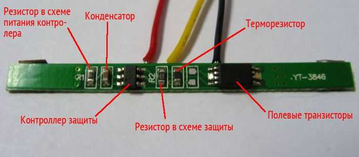
The DW01 chip itself is six-legged, and two field-effect transistors are structurally made in one package in the form of an 8-legged assembly.
Pin 1 and 3 control the discharge protection switches (FET1) and overcharge protection switches (FET2), respectively. Threshold voltages: 2.4 and 4.25 Volts. Pin 2 is a sensor that measures the voltage drop across field-effect transistors, which provides protection against overcurrent. The transition resistance of transistors acts as a measuring shunt, so the response threshold has a very large scatter from product to product.
The whole scheme looks something like this: 
The right microcircuit marked 8205A is the field-effect transistors that act as keys in the circuit.
S-8241 Series
SEIKO has developed specialized chips to protect lithium-ion and lithium-polymer batteries from overdischarge/overcharge. To protect one can, integrated circuits of the S-8241 series are used. 
Overdischarge and overcharge protection switches operate at 2.3V and 4.35V, respectively. Current protection is activated when the voltage drop across FET1-FET2 is equal to 200 mV.
AAT8660 Series
LV51140T
A similar protection scheme for lithium single-cell batteries with protection against overdischarge, overcharge, and excess charge and discharge currents. Implemented using the LV51140T chip. 
Threshold voltages: 2.5 and 4.25 Volts. The second leg of the microcircuit is the input of the overcurrent detector (limit values: 0.2V when discharging and -0.7V when charging). Pin 4 is not used.
R5421N Series
The circuit design is similar to the previous ones. In operating mode, the microcircuit consumes about 3 μA, in blocking mode - about 0.3 μA (letter C in the designation) and 1 μA (letter F in the designation). 
The R5421N series contains several modifications that differ in the magnitude of the response voltage during recharging. Details are given in the table:
SA57608
Another version of the charge/discharge controller, only on the SA57608 chip. 
The voltages at which the microcircuit disconnects the can from external circuits depend on the letter index. For details, see the table:
The SA57608 consumes a fairly large current in sleep mode - about 300 µA, which distinguishes it from the above-mentioned analogues for the worse (where the current consumed is on the order of fractions of a microampere).
LC05111CMT
And finally, we offer an interesting solution from one of the world leaders in the production of electronic components On Semiconductor - a charge-discharge controller on the LC05111CMT chip. 
The solution is interesting in that the key MOSFETs are built into the microcircuit itself, so all that remains of the add-on elements are a couple of resistors and one capacitor.
The transition resistance of the built-in transistors is ~11 milliohms (0.011 Ohms). The maximum charge/discharge current is 10A. The maximum voltage between terminals S1 and S2 is 24 Volts (this is important when combining batteries into batteries).
The microcircuit is available in the WDFN6 2.6x4.0, 0.65P, Dual Flag package.
The circuit, as expected, provides protection against overcharge/discharge, overload current, and overcharging current.
Charge controllers and protection circuits - what's the difference?
It is important to understand that the protection module and charge controllers are not the same thing. Yes, their functions overlap to some extent, but calling the protection module built into the battery a charge controller would be a mistake. Now I’ll explain what the difference is.
The most important role of any charge controller is to implement the correct charge profile (usually CC/CV - constant current/constant voltage). That is, the charge controller must be able to limit the charging current at a given level, thereby controlling the amount of energy “poured” into the battery per unit time. Excess energy is released in the form of heat, so any charge controller gets quite hot during operation.
For this reason, charge controllers are never built into the battery (unlike protection boards). The controllers are simply part of a proper charger and nothing more.
In addition, not a single protection board (or protection module, whatever you want to call it) is capable of limiting the charge current. The board only controls the voltage on the bank itself and, if it goes beyond predetermined limits, opens the output switches, thereby disconnecting the bank from the outside world. By the way, short circuit protection also works on the same principle - during a short circuit, the voltage on the bank drops sharply and the deep discharge protection circuit is triggered.
Confusion between the protection circuits for lithium batteries and charge controllers arose due to the similarity of the response threshold (~4.2V). Only in the case of a protection module is the can completely disconnected from the external terminals, and in the case of a charge controller is it switched to a voltage stabilization mode and a gradual decrease in the charging current.


Why does a lithium-ion battery need a charge controller?
Many readers of the site ask about what a lithium-ion battery charge controller is and what it is needed for. This issue was briefly mentioned in materials describing the various types of lithium batteries. This type of battery almost always includes a charging controller, also called a Battery Monitoring System (BMS) protection board. In this article we will take a closer look at what this device is and how it functions.
The simplest version of a lithium-ion battery charging controller can be seen if you disassemble the battery of a tablet computer or phone. It consists of a can (battery cell) and a BMS protection circuit board. This is the charging controller, which can be seen in the photo below.
The basis here is the security controller chip. Field-effect transistors are used to separately control protection when charging and discharging the battery cell.
The purpose of the protection controller is to ensure that the bank is not charged above a voltage of 4.2 volts. The lithium battery cell has a nominal voltage of 3.7 volts. Overcharging and exceeding voltage above 4.2 volts can cause the cell to fail.
In smartphone and tablet batteries, the BMS board monitors the charging and discharging process of one element (cell). There are several such cans in laptop batteries. Usually from 4 to 8.

The controller also monitors the discharge process of the battery cell. When the voltage drops below the threshold (usually 3 volts), the circuit disconnects the bank from the current consumer. As a result, the battery-powered device simply turns off.
Among other functions of the charging controller, it is worth noting short circuit protection. Some BMS protection boards include a thermistor to protect the battery cell from overheating.
BMS protection boards for lithium-ion batteries
The controller discussed above is the simplest option for BMS protection. In fact, there are many more varieties of such boards and some are quite complex and expensive. Depending on the scope of application, the following types are distinguished:
- For portable mobile electronics;
- For household appliances;
- Used in renewable energy sources.
Often such BMS protection boards can be found in systems with solar panels and in wind generators. There, as a rule, the upper threshold for voltage protection is 15, and the lower is 12 volts. The battery itself produces 12 volts in normal mode. An energy source (for example, a solar panel) is connected to the battery. The connection is made via a relay.

When the battery voltage increases above 15 volts, the relays are activated and the charging circuit is opened. After this, the energy source operates on the ballast provided for this purpose. As experts say, in the case of solar panels, this can give unwanted side effects.
In the case of wind generators, BMS controllers are required. Charging controllers for household appliances and mobile devices have significant differences. But the battery controllers for laptops, tablets and phones have the same circuit. The only difference is the number of controlled battery cells.


